Electric motor malfunctions and their elimination. Malfunctions of electric motors: classification, diagnosis and identification of the problem, methods of elimination and advice from specialists. Electric motor malfunctions and ways to eliminate them
Electric motors are ubiquitous in industry and are becoming increasingly complex, which can often make it difficult to keep them operating at peak efficiency. It is important to remember that the causes of faults in electric motors and drives are not limited to one area of specialization: they can be both mechanical and electrical in nature. And only the right knowledge saves you from costly downtime and extended service life.
The most common malfunctions of electric motors are damage to winding insulation and wear of bearings., arising for many different reasons. This article focuses on early detection of the 13 most common causes of insulation failure and bearing failure.
Power quality
Variable Frequency Drives
Mechanical reasons
Power quality
1. Transient voltage
 Transient voltages can come from a variety of sources both within and outside the plant. The turning on and off of nearby loads, power factor correction capacitor banks, or even weather events can all create transient voltages on distribution networks. These processes with arbitrary amplitude and frequency can destroy or damage the insulation of electric motor windings.
Locating the source of transients can be challenging because they occur irregularly and their effects can manifest in different ways. For example, transients may appear in control cables and will not necessarily cause damage to the equipment itself, but they may interfere with its operation.
Impact: Damage to motor winding insulation leads to early faults and unplanned downtime.
Criticality: high.
2. Voltage asymmetry
 Three-phase distribution networks often supply single-phase loads. Resistance or load asymmetry can cause voltage asymmetry on all three phases. Possible faults may be in the motor wiring, at the motor terminals, as well as in the windings themselves. This asymmetry can cause overloads in each phase circuit of a three-phase network. In short, the voltage on all three phases should always be the same.
Impact: asymmetry causes overcurrents in one or more phases, which cause overheating and damage to the insulation.
Fluke 435-II three-phase power quality analyzer.
Criticality: average.
3. Harmonic distortion
 Simply put, harmonics are any unwanted additional high-frequency voltage or current fluctuations entering the windings of an electric motor. This additional energy is not used to rotate the motor shaft, but circulates in the windings and ultimately leads to a loss of internal energy. These losses are dissipated as heat, which degrades the insulating properties of the windings over time. Some harmonic distortion in the current waveform is normal for systems powering electronic loads. Harmonic distortion can be measured with a power quality analyzer by monitoring currents and temperatures on transformers to ensure they are not overloaded. For each harmonic, an acceptable level of distortion is established, which is regulated by the IEEE 519-1992 standard.
Impact: Reduced motor efficiency results in additional costs and increased operating temperature.
Measurement and diagnostic tool: Fluke 435-II three-phase power quality analyzer.
Criticality: average.
Variable Frequency Drives
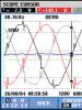
4. Reflections on drive output PWM signals
 Variable frequency drives use pulse width modulation (PWM) to control the output voltage and frequency of the motor supply. Reflections occur due to a mismatch between the source and load impedances. Impedance mismatches can occur as a result of improper installation, incorrect component selection, or equipment deterioration over time. The reflection peak in the drive circuit can reach the DC bus voltage level.
Impact: Damage to the motor winding insulation leads to unplanned downtime.
Measuring and diagnostic device: Fluke 190-204 ScopeMeter®, 4-channel, high-sampling-rate handheld oscilloscope.
Criticality: high.
5. Standard deviation of current
Impact: arbitrary opening of the circuit due to the passage of current through the protective grounding.
Measuring and diagnostic device: Fluke 190-204 ScopeMeter oscilloscope with wideband (10 kHz) current clamps (Fluke i400S or similar).
Criticality: low.
6. Work overload
 Motor overload occurs when it operates under increased load. The main signs of an overloaded motor are excessive current consumption, insufficient torque and overheating. Excessive heat generation from an electric motor is the main cause of motor failure. When a motor is overloaded, individual motor components - including bearings, windings and other parts - may operate normally, but the motor will overheat. Therefore, troubleshooting should begin by checking whether the electric motor is overloaded. Since 30% of all motor failures are caused by motor overload, it is important to understand how to measure and determine motor overload.
Impact: premature wear of the electrical and mechanical components of the electric motor, leading to irreversible failure.
Measurement and diagnostic tool: Fluke 289 digital multimeter.
Criticality: high.
7. Misalignment
 Misalignment occurs when the drive shaft is not aligned correctly with the load or the gear that connects them is misaligned. Many experts believe that a flex joint eliminates and compensates for misalignment, however, a flex joint only protects the transmission itself from misalignment. Even with a flexible connection, an out-of-center shaft will transmit damaging cyclic forces along its length to the motor, causing increased wear on the motor and increasing the actual mechanical load. In addition, misalignment can cause vibration of the shafts of both the load and the electric drive. There are several types of misalignment:
- Angular misalignment: the shaft axes intersect, but are not parallel;
- Parallel offset: the shaft axes are parallel, but not coaxial;
- Compound offset: a combination of angular and parallel offsets. (Note: almost always the misalignment is complex, but practitioners consider them as the sum of the displacement components, since it is easier to eliminate the misalignment separately - the angular and parallel components).
Influence:
Measuring and diagnostic device: Fluke 830 laser shaft alignment tool.
Criticality: high.
8. Shaft imbalance
 Imbalance is a condition of a rotating part when the center of mass is not located on the axis of rotation. In other words, when the center of gravity is somewhere on the rotor. Although it is impossible to completely eliminate engine imbalance, you can determine if it is outside of acceptable limits and take steps to correct the situation.
Imbalance can be caused by various reasons:
- accumulation of dirt;
- lack of balancing weights;
- deviations in production;
- unequal mass of motor windings and other factors associated with wear.
A vibration tester or vibration analyzer will help determine whether a rotating mechanism is balanced or not.
Influence: premature wear of the mechanical components of the drive, causing premature failures.
Measuring and diagnostic device: Fluke 810 vibration meter.
Criticality: high.
9. Shaft looseness
 Looseness occurs due to excessive clearance between parts. Looseness can occur in several places:
- Rotational looseness occurs due to excessive play between rotating and stationary machine parts, such as a bearing.
- Non-rotational looseness occurs between two normally stationary parts, such as between a support and a base or a bearing housing and a machine.
As with all sources of vibration, it is important to be able to identify looseness and correct the problem to avoid damage. You can determine if there is looseness in a rotating machine using a vibration tester or vibration analyzer.
Influence: accelerated wear of rotating components causing mechanical failure.
Measuring and diagnostic device: Fluke 810 vibration meter.
Criticality: high.
10. Bearing wear
 A bad bearing has increased friction, runs hotter, and has reduced efficiency due to mechanical problems, lubrication problems, or wear. Bearing failure can be the result of various factors:
When bearing failures begin to occur, this also causes a cascading effect that accelerates engine failure. 13% of engine failures are caused by bearing failures, and more than 60% of plant mechanical failures are caused by bearing wear, so it's important to know how to troubleshoot these potential problems.
Influence: accelerated wear of rotating components leads to bearing failure.
Measuring and diagnostic device: Fluke 810 vibration meter.
Criticality: high.
Factors associated with improper installation
11. Loose base
 A loose fit is caused by an uneven mounting base of the motor or driven component or an uneven mounting surface on which the mounting base rests. This condition can create an unfortunate situation in which tightening the mounting bolts actually introduces new loads and misalignment. A loose support often occurs between two diagonally positioned mounting bolts, as is the case with an uneven chair or table that rocks diagonally. There are two types of loose base:
- Parallel loose base fit - occurs when one mounting support is located higher than the other three;
- Angular base leak occurs when one of the mounting supports is not parallel or perpendicular to the mounting surface.
In both cases, a loose base may be caused by irregularities in the mechanism's mounting support or in the mounting base on which the support is located. In any case, it is necessary to find and eliminate a loose fit before centering the shaft. A quality laser alignment tool can determine if the base of a given rotating machine is loose.
Influence: misalignment of mechanical drive components.
Measuring and diagnostic device: Fluke 830 laser shaft alignment tool.
Criticality: average.
12. Piping tension
 Piping tension is a condition in which new loads, tensions and forces acting on the rest of the equipment and infrastructure are transferred back to the motor and drive, resulting in misalignment. The most common example of this is simple motor/pump circuits where something is acting on the piping, such as:
- displacement in the foundation;
- a recently installed valve or other component;
- an object striking, bending or simply pressing on the pipe;
- Broken or missing pipe fixtures or wall fittings.
These forces can cause angular or shearing effects, which in turn cause the motor/pump shaft to move. For this reason, it is important to check machine alignment not only during installation - accurate alignment is a temporary condition and may change over time.
Influence: misalignment of the shaft and subsequent loads on rotating components, leading to premature failures.
Measuring and diagnostic device: Fluke 830 laser shaft alignment tool.
Criticality: low.
13. Shaft voltage
 When the voltage on the motor shaft exceeds the insulating characteristics of the bearing lubricant, breakdown occurs to the outer bearing, causing pitting and groove formation in the bearing raceway. The first signs of a problem are noise and overheating that occurs as the bearings lose their original shape, as well as the appearance of metal chips in the lubricant and increased bearing friction. This can lead to bearing failure after just a few months of operation of the electric motor. Bearing failure is a costly problem in both motor rebuilding and equipment downtime, so preventing it by measuring shaft voltage and bearing current is an important part of diagnosis. Shaft voltage is only present when the motor is energized and rotating. A carbon brush mounted on the probe allows you to measure the voltage on the shaft as the electric motor rotates.
Influence: Arcing on the bearing surface causes pitting and groove formation, which in turn leads to excessive vibration and subsequent bearing failure.
Measuring and diagnostic device: Fluke-190-204 ScopeMeter isolated 4-channel handheld oscilloscope, AEGIS probe with carbon brushes for measuring shaft voltage.
Criticality: high.
Four Strategies for Success
Electric motor control systems are used in critical processes in factories. Equipment failure can lead to large financial losses associated with both the potential replacement of the electric motor and its parts, and the downtime of systems that depend on this electric motor. By equipping service engineers and technicians with the knowledge they need, prioritizing work, and performing preventative maintenance to monitor equipment and correct hard-to-find problems, workload-induced failures can often be avoided and downtime costs can be reduced.
There are four key strategies to eliminate or prevent premature motor and rotating component failures:
- Record operating conditions, equipment specifications, and operating tolerance ranges.
- Regular collection and recording of critical measurements during installation, before and after maintenance.
- Create an archive of reference measurements for trend analysis and state change detection.
- Plotting individual measurements to identify major trends. Any change in the trend line greater than +/- 10-20% (or any other specified amount, depending on the performance or criticality of the system) should be investigated to determine the cause of the problems.
The main reasons for the breakdown of electric motors include violation of the rules of their operation, as well as aging and wear of mechanism parts. All defects in electric motors can be divided into two types - mechanical and electrical. The electrical type includes damage to the conductive parts of windings or insulation, damage to core sheets and slip rings. Various distortions of the housing and parts of the electric motor, loosening of fastening connections, damage to the surfaces of parts or their shape are classified as mechanical defects. If mechanical damage to electric motors is quite easy and simple to detect even visually, then electrical faults can only be detected by carrying out special measurements, focusing on indirect signs. Only after determining the exact cause of the device malfunction, a decision is made on the method and scope of repair work.
Below is an approximate list of the main causes of failure of electric motors, as well as signs of these malfunctions:
| Motor fault | Symptoms of a problem |
| Fan malfunction or increased mains voltage. | The motor load is normal, however, the active stator steel overheats |
| The rotor touching the stator or the presence of burrs lead to local short circuits between the active steel sheets; breakdown of the winding to the housing or short circuits in the stator winding lead to burnout and melting of the active steel teeth. | Active steel becomes very hot even when the electric motor is idling, as well as at normal mains voltage. |
| The normal ventilation of the electric motor is disrupted; it is overloaded at rated power due to low voltage at the motor outputs. The stator winding is connected in a delta rather than a star. | The stator winding overheats uniformly. |
| The stator winding overheats greatly. Uneven current in individual phases. Loud noise when the electric motor is running. | Short or turn circuit between two phases. |
| Poor contact in the rotor circuit (at the zero point or in the soldering of the frontal parts of the winding, in connections between parallel groups, in connections between rods), in winding connections with slip rings, in connections between the starting rheostat and slip rings. | The motor stator and rotor overheat. There is current pulsation in the stator and strong noise when the electric motor is running.The engine does not develop the rated speed and starts poorly. The rotation torque does not reach the nominal values. |
| A blown fuse results in no current flowing to the stator. | The electric motor does not start. |
| There is a break in the stator winding or a break in the phase of the network circuit. If this happens while the electric motor is running, the rotor or stator winding may completely burn out. | The electric motor does not start, makes uncharacteristic noises and jerks when turning manually. Lack of current in one stator phase. |
| The presence of a break in several phases in the connecting wires between the starting rheostat and the rotor, as well as directly in the starting rheostat. Displacement of the bearing risers or shields, or severe wear of the bearing shells lead to a significant attraction of the rotor to the stator (one-sided). | The electric motor does not start even with normal voltage at the stator terminals, as well as with the same current in the three phases of the stator. |
| The electric motor does not start with a load; without load and with a squirrel-cage rotor - it starts. | |
| Sparking during operation of the electric motor, strong heating of the brushes and commutator. | The brushes are not installed correctly in the brush holders or are heavily worn; poor contact between the fittings and the brushes is ensured; there is a discrepancy between the sizes of the brushes and the brush holder cages. |
| The bodies or raceways are destroyed. | Strong knocking sounds are detected in the rolling bearings. |
| Incorrect and inaccurate alignment of the engine shafts has been allowed, there has been misalignment of the coupling halves, and there have been violations of the rotor balancing using couplings and pulleys. | When the electric motor operates, strong vibrations are observed. |
Have you discovered that your diesel generator is malfunctioning or has stopped starting altogether? First of all, it is necessary to inspect the equipment for visible problems. In this article we will look at the main types of malfunctions of diesel generator sets (diesel generator sets), their causes, and also tell you how to eliminate them.
Inspecting the diesel generator before starting
The first thing to do if a problem is detected is to check the generator for external damage (which, by the way, is recommended before each start-up): if you see cracks, dents or other flaws on the housing, then most likely the cause of the failure is mechanical damage. Also make sure that there are no foreign objects inside the device.
6 most common types of diesel generator set malfunctions
- generator won't start
- does not output voltage
- stalls during operation
- uses more oil than it should
- There is a loud knocking sound when the engine is running
- strange color of exhaust gases (black, white and blue)
Let's look at each type in detail.
The generator does not start
There could be several reasons:
- The fuel pump is broken: this is indicated by low or uneven fuel supply.
- The cold start device is broken. This is most likely due to waxing of the fuel, which usually occurs in cold temperatures. To prevent this from happening to your equipment, use seasonal fuel and do not use the device in cold weather.
- Fuel is of low quality or contaminated. To avoid this, use only proven, clean, undiluted fuel: saving on it can lead to serious repair costs.
- The starter has failed, resulting in insufficient rotation speed. There are two reasons: a) the use of low quality oil, b) a weak battery.
The generator does not produce voltage
Attention! Before checking any electrical part, completely de-energize the equipment to avoid electric shock.
The diesel generator works, but does not produce voltage: perhaps the contacts are loose or missing, or there is a problem in the brushes. Check their connection according to the instructions.
Another reason may be a problem with the voltage regulator or winding wear: inspect their condition.

The diesel generator stalls during operation
In this case, there are 7 main reasons, some of which you can identify and eliminate yourself:
- there is not enough fuel in the tank
- air got into the fuel
- additional resistance in the fuel supply system or the system for draining excess fuel into the tank, as well as in the intake or exhaust systems
- dirty air filter
- injector failure
- incorrect idle speed setting
The generator uses more oil than it should
Check the oil system for depressurization: oil may leak into other systems, for example, into the fuel system. To prevent depressurization, use only high-quality oils.
A loud knocking sound is heard while the engine is running
Most often, knocking indicates wear or breakdown of the following parts:
- injectors
- valve springs
- piston rings
- cylinder-piston group
- crankshaft bearing
- camshaft
If the listed parts are in order, check the valve clearance adjustment, timing mechanism and injection timing setting. Is that normal too? Then the problem is the presence of air in the fuel system or poor quality fuel.

Strange color of exhaust gases
Every year, gasoline engines are increasingly being replaced by electric motors installed in a new type of car called electric vehicles. However, just like internal combustion engines, electric powertrains can break down, causing problems with vehicle performance. The majority of electric motor malfunctions occur due to severe wear of mechanism parts and aging of materials, which is reinforced by improper operation of such a vehicle. There can be many reasons for the appearance of characteristic problems, and we will now tell you about some (the most common) ones.
Causes of electric motor malfunction
All possible malfunctions of an electric vehicle engine can be divided into mechanical and electrical. The causes of mechanical problems include distortions of the electric motor housing and its individual parts, loosening of fastenings and damage to the surface of the constituent elements or their shape. In addition, overheating of the bearings, leakage of oil and abnormal operating noise are common problems. The most typical malfunctions of the electrical part include short circuits within the windings of the electric motor, as well as between them, short circuits of the windings to the housing and breaks in the windings or in the external circuit, that is, in the supply wires and starting equipment.

As a result of the occurrence of certain problems, The following malfunctions may occur in the operation of the vehicle: inability to start the motor, dangerous heating of the windings, abnormal motor speed, unnatural noise (hum or knock), unequal current in individual phases.
Typical motor problems
Let's look at electric motor breakdowns in more detail, identifying their possible causes.
AC motor
Problem: when connected to the power supply, the electric motor does not develop the rated speed and makes unnatural sounds, and when the shaft is turned by hand, uneven operation is observed. The reason for this behavior is most likely a break in two phases when connecting the stator windings with a triangle, or a break when connecting a star.
If the engine rotor does not rotate, makes a strong hum and heats up above the permissible level, we can say with confidence that the stator phase is to blame. When the engine hums (especially when trying to start), and the rotor rotates at least slowly, the cause of the problem is often a break in the rotor phase.
 It happens that with a rated load on the shaft, the electric motor operates stably, but its rotation speed is slightly lower than the rated one, and the current in one of the stator phases is increased. As a rule, this is a consequence of a phase failure when connecting the windings with a delta.
If at idle speed of the electric motor there is local overheating of the active steel of the stator, this means that due to damage to the inter-sheet insulation or burnout of the teeth due to damage to the winding, the sheets of the stator core are closed to each other.
When the stator winding overheats in certain places, when the engine cannot develop the rated torque and hums strongly, the cause of this phenomenon should be sought in a turn short circuit of one phase of the stator winding or an interphase short circuit in the windings.
If the entire electric motor overheats evenly, then the fan of the ventilation system is faulty, and overheating of the plain bearings with ring lubrication is due to the one-sided attraction of the rotors (due to excessive wear of the liner) or poor fit of the shaft to the liner. When a rolling bearing overheats and produces abnormal noise, it is likely that the cause is contamination of the lubricant, excessive wear of the rolling elements and races, or imprecise alignment of the unit shafts.
Knocking in the plain bearing and in the rolling bearing is explained by serious wear of the liner or destruction of the tracks and rolling elements, and increased vibration is a consequence of imbalance of the rotor due to interaction with pulleys and couplings, or the result of inaccurate alignment of the unit shafts and misalignment of the connecting coupling halves.
A DC electric motor may also have its own characteristic faults:
 Under serious load, the machine’s armature may not rotate, and if you try to turn it by external force, the engine will run “staggered.” Reasons: poor contact or complete break in the excitation circuit, interturn or short circuits inside the independent excitation winding. Under conditions of rated values of the network voltage and excitation current, the armature rotation speed may be less or more than the established norm. In this case, the culprits for this situation are the brushes, shifted from the neutral position in the direction of rotation of the shaft or against it.
It may also be that the brushes of one sign spark a little stronger than the brushes of another sign. Perhaps the distances between the rows of brushes around the circumference of the commutator are not the same, or there is an interturn short circuit in the windings of one of the main or additional “pluses”. If the sparking of the brushes is also accompanied by blackening of the commutator plates, which are located at a certain distance from each other, then the culprit for this situation is most likely poor contact or a short circuit in the armature winding. Also, do not forget about the possibility of a break in the armature coil connected to the blackened plates.
In cases where only every second or third plate of the collector darkens, the cause of the malfunction may be a weakened compression of the collector or protruding micanite of the insulating tracks. Brushes can spark even with normal heating of the motor and a fully functional brush apparatus, which is explained by unacceptable wear of the commutator.
The reasons for increased sparking of brushes, overheating of the commutator and darkening of most of it are usually the insulation tracks (they say the commutator “beats”). When the motor armature rotates in different directions, the brushes also spark with different intensities. There is only one reason - the displacement of the brushes from the center.
 If increased sparking of the brushes is observed on the commutator, then it is worth checking the tightness of their fit, as well as conducting diagnostics for the presence of defects in the working surface of the brushes. In addition, the reason may be uneven pressure of the brushes or their jamming in the brush holder. Naturally, if any of the listed problems are detected, it must be properly eliminated, but quite often only highly qualified specialists can do this.
Troubleshooting electric motor
High-quality overhaul of electric motors can only be carried out at specialized enterprises. During routine repair work, the power unit is dismantled and worn parts are subsequently partially replaced. Let's look at the order of performing all actions using the example of an asynchronous electric motor.
At the initial stage, using a screw puller, remove the pulley or coupling half from the electric motor pulley. After this, you need to unscrew the bolts securing the fan casing and remove it. Next, using the same screw puller, you need to unscrew the locking screw and remove the fan itself. If necessary, the same tool can be used to remove the bearings from the motor shaft, and then, by unscrewing the fastening bolts, remove their covers.
After this, you should unscrew the bolts securing the bearing shields and remove these shields with light blows of a hammer through a wooden spacer. To avoid damaging the steel and windings, a cardboard spacer is placed in the air gap, onto which the rotor is lowered. Reassembling the electric motor is carried out in the reverse order.
 After repair work is completed (the specifics depend on the nature of the breakdown), the electric motor should be tested. To do this, simply rotate the rotor by holding the pulley, and if the assembly is done correctly, the unit should rotate easily. If everything is normal, the motor is installed in place, connected to the network and checked for operation in idle mode, after which the motor is connected to the machine shaft and tested again. Let's look at options for troubleshooting an electric motor using the example of some typical breakdowns.
So, let's imagine that the motor does not start due to a lack of voltage in the network, the machine is turned off or the fuses are blown. The presence of voltage can be checked using a special device - an AC voltmeter with a 500 V scale, or using a low-voltage indicator. The problem can be resolved by replacing the blown fuses. Note!If at least one fuse blows, the engine will make a characteristic hum.
A phase break in the stator winding can be detected using a megger, but before doing this, all ends of the motor windings must be freed. If a break is detected inside the winding phase, the engine will have to be sent for professional repair. The acceptable norm for reducing the voltage at the motor terminals when starting it is considered to be 30% of the nominal value, which is caused by losses in the network, insufficient power of the transformer or its overload.
If you notice a decrease in voltage at the electric motor terminals, you need to replace the supply transformer or increase the cross-section of the supply line wires. Lack of power supply contact in one of the stator windings (phase loss) causes an increase in current in the element windings and a decrease in the number of revolutions. If you leave the motor running on two windings, it will simply burn out.
In addition to the listed electrical problems, electric motors can also suffer from mechanical problems. Thus, excessive heating of the bearings is often caused by improper assembly of these parts, poor alignment of the motor, contamination of the bearings, or excessive wear of the balls and rollers.
 In any case, before proceeding to direct action, you should conduct a complete diagnosis of the electric motor and the parts interacting with it. The inspection procedure begins with checking the battery, and if it is in good condition, then the next step is to check the power supply to the electrical circuit of the controller (the computer that controls the rotation speed of the electric motor). It is quite possible that you will find a broken wire along the path from the battery to the board. The breakdown of an electronic board is not a frequent occurrence, but if there is even the slightest doubt about its serviceability, then it is better to immediately visually assess the condition of the part. If there has been strong heating of the board elements, you will immediately notice blackened and swollen areas with possible leaks.
In the case where the car owner has at least minimal knowledge in the field of electronics, he can independently check fuses, semiconductor parts (like diodes and transistors), all contacts, capacitances and soldering quality.
When the ECU output has operating voltage in the on state, then, as a rule, the cause of the malfunction should be sought in the electric motor itself. The complexity of repairing the unit depends on the specific malfunction and type of mechanism. So, when examining AC electric motors with rotary power, first of all, it is necessary to check the contact brushes, because they are most often the cause of breakdowns of motors of this type. After this, you should check the windings for breaks or short circuits. In the event of a break, the tester will not show any resistance value, and in the event of a short circuit, the resistance indicator will correspond to zero or one Ohm.
Having discovered a malfunction, it, of course, needs to be eliminated. This can be done either by repairing and replacing failed parts (for example, a brush), or by replacing the entire motor with a working analogue.
An important point when working with the regulator RDUK is knowledge of its main faults and ways to eliminate them. There are about eight types of regulator malfunctions, and everyone who works with similar regulators needs to know about them, and not only know, but also be able to correct them.
Types of faults and solutions:
- The pilot spring is completely weakened, but the output pressure reaches or exceeds 20 percent operating pressure: the regulator's adjustable element (pilot) is leaking. The sealing surfaces of the seat and valve are inspected, and if necessary, the rubber gasket of the valve is replaced.
- The outlet pressure drops to zero: the regulator diaphragm is ruptured; the diaphragm must be replaced.
- The output pressure is constantly increasing: pilot diaphragm rupture, seat clogging or sticking of the pusher, pilot spool in the guides. It is necessary to replace the membrane, clean the seat and eliminate the sticking of the pusher.
- The outlet pressure, when adjusted within the range (0.2-0.6 kg/cm²), fluctuates greatly: install a throttle on the impulse tube from the regulator's membrane chamber to the main gas pipeline, and if fluctuations persist, reduce the sensitivity of the pilot by installing a denser (stiffer) spring .
- The outlet pressure fluctuates greatly at low gas consumption, independent of the setting pressure. The reason may be hidden in the rather large throughput of the regulator. If elimination of oscillations is not achieved by installing a throttle on the impulse tube from the regulator's membrane chamber to the main gas pipeline, then reduce the inlet pressure and, if necessary, replace the regulator seat and valve with smaller sizes.
- The output pressure gradually decreases, at times increases sharply and again decreases to zero: freezing of the spool and pilot seat, this is eliminated by heating the pilot with a rag moistened with hot water.
- The output pressure gradually decreases and preloading the pilot spring does not increase it: clogged filter or pilot seat hole, loss of spool sealing rubber, breakage of the pilot tuning spring. The filter should be cleaned and blown out, the rubber band and spring should be replaced with new ones.
- The outlet pressure changes simultaneously with the change in inlet pressure: the installation locations of the throttle on the impulse tube from the membrane chamber of the regulator to the main gas pipeline and the dolphin throttle are mixed up, or the throttles are not installed at all. It is necessary to check whether the throttles are installed and whether this is done correctly.
All this must be constantly remembered, otherwise serious problems with the operation of gas equipment may arise.