Manual ultrasonic testing (UT) of welded joints of vessels and pipelines made of pearlitic and martensitic-ferritic steels. Ultrasonic testing of butt ring welded joints of pipe systems and pipelines Ultrasonic testing
GOST R 55724-2013
NATIONAL STANDARD OF THE RUSSIAN FEDERATION
NON-DESTRUCTIVE CONTROL. WELDED CONNECTIONS
Ultrasonic methods
Non-destructive testing. Welded joints. Ultrasonic methods
Date of introduction 2015-07-01
Preface
Preface
1 DEVELOPED by the Federal State Enterprise "Research Institute of Bridges and Flaw Detection of the Federal Agency of Railway Transport" (Research Institute of Bridges), the State Scientific Center of the Russian Federation "Open Joint Stock Company" Research and Production Association "Central Research Institute of Mechanical Engineering Technology" (JSC NPO "TsNIITMASH" "), Federal State Autonomous Institution "Research and Training Center "Welding and Control" at Moscow State Technical University named after N.E. Bauman"
2 INTRODUCED by the Technical Committee for Standardization TC 371 “Non-Destructive Testing”
3 APPROVED AND ENTERED INTO EFFECT by Order of the Federal Agency for Technical Regulation and Metrology dated November 8, 2013 N 1410-st
4 INTRODUCED FOR THE FIRST TIME
5 REPUBLICATION. April 2019
The rules for the application of this standard are established in Article 26 of the Federal Law of June 29, 2015 N 162-FZ "On Standardization in the Russian Federation" . Information about changes to this standard is published in the annual (as of January 1 of the current year) information index "National Standards", and the official text of changes and amendments is published in the monthly information index "National Standards". In case of revision (replacement) or cancellation of this standard, the corresponding notice will be published in the next issue of the monthly information index "National Standards". Relevant information, notices and texts are also posted in the public information system - on the official website of the Federal Agency for Technical Regulation and Metrology on the Internet (www.gost.ru)
1 area of use
This standard establishes methods for ultrasonic testing of butt, corner, lap and T-joints with full penetration of the root of the weld, made by arc, electroslag, gas, gas press, electron beam, laser and flash butt welding or combinations thereof, in welded products made of metals and alloys for identifying the following discontinuities: cracks, lack of penetration, pores, non-metallic and metallic inclusions.
This standard does not regulate methods for determining the actual size, type and shape of identified discontinuities (defects) and does not apply to the control of anti-corrosion surfacing.
The need for and scope of ultrasonic testing, types and sizes of discontinuities (defects) to be detected are established in standards or design documentation for products.
2 Normative references
This standard uses normative references to the following standards:
GOST 12.1.001 System of occupational safety standards. Ultrasound. General safety requirements
GOST 12.1.003 System of occupational safety standards. Noise. General safety requirements
GOST 12.1.004 System of occupational safety standards. Fire safety. General requirements
GOST 12.2.003 System of occupational safety standards. Production equipment. General safety requirements
GOST 12.3.002 System of occupational safety standards. Production processes. General safety requirements
GOST 2789 Surface roughness. Parameters and characteristics
GOST 18353 * Non-destructive testing. Classification of types and methods
________________
* No longer valid. GOST R 56542-2015 is valid.
GOST 18576-96 Non-destructive testing. Railway rails. Ultrasonic methods
GOST R 55725 Non-destructive testing. Ultrasonic piezoelectric transducers. General technical requirements
GOST R 55808 Non-destructive testing. Ultrasonic transducers. Test methods
Note - When using this standard, it is advisable to check the validity of the reference standards in the public information system - on the official website of the Federal Agency for Technical Regulation and Metrology on the Internet or using the annual information index "National Standards", which was published as of January 1 of the current year, and on issues of the monthly information index "National Standards" for the current year. If an undated reference standard is replaced, it is recommended that the current version of that standard be used, taking into account any changes made to that version. If a dated reference standard is replaced, it is recommended to use the version of that standard with the year of approval (adoption) indicated above. If, after the approval of this standard, a change is made to the referenced standard to which a dated reference is made that affects the provision referred to, it is recommended that that provision be applied without regard to that change. If the reference standard is canceled without replacement, then the provision in which a reference to it is given is recommended to be applied in the part that does not affect this reference.
3 Terms and definitions
3.1 The following terms with corresponding definitions are used in this standard:
3.1.19 SKH diagram: Graphic representation of the dependence of the detection coefficient on the depth of a flat-bottomed artificial reflector, taking into account its size and type of transducer.
3.1.20 rejection sensitivity level: The level of sensitivity at which a decision is made to classify an identified discontinuity as a “defect”.
3.1.21 diffraction method: A method of ultrasonic testing using the reflection method, using separate transmitting and receiving transducers and based on receiving and analyzing the amplitude and/or time characteristics of wave signals diffracted by a discontinuity.
3.1.22 reference sensitivity level (fixation level): The level of sensitivity at which discontinuities are recorded and their acceptability is assessed based on their conventional size and quantity.
3.1.23 reference signal: A signal from an artificial or natural reflector in a sample of a material with specified properties or a signal that has passed through a controlled product, which is used in determining and adjusting the reference level of sensitivity and/or measured discontinuity characteristics.
3.1.24 reference sensitivity level: The sensitivity level at which the reference signal has a specified height on the flaw detector screen.
3.1.25 depth gauge error: The error in measuring the known distance to the reflector.
3.1.26 search sensitivity level: The level of sensitivity set when searching for discontinuities.
3.1.27 maximum sensitivity of control using the echo method: Sensitivity, characterized by the minimum equivalent area (in mm) of the reflector that can still be detected at a given depth in the product for a given equipment setting.
3.1.28 entry angle: The angle between the normal to the surface on which the transducer is installed and the line connecting the center of the cylindrical reflector to the beam exit point when the transducer is installed in the position at which the amplitude of the echo signal from the reflector is greatest.
3.1.29 conditional size (length, width, height) of the defect: The size in millimeters corresponding to the zone between the extreme positions of the transducer, within which the signal from a discontinuity is recorded at a given sensitivity level.
3.1.30 conventional distance between discontinuities: The minimum distance between transducer positions at which the amplitudes of echo signals from discontinuities are fixed at a given sensitivity level.
3.1.31 conditional sensitivity of control using the echo method: Sensitivity, which is determined by the CO-2 (or CO-3P) measure and is expressed by the difference in decibels between the reading of the attenuator (calibrated amplifier) at a given flaw detector setting and the reading corresponding to the maximum attenuation (gain) at which a cylindrical hole with a diameter of 6 mm at a depth 44 mm is fixed by flaw detector indicators.
3.1.32 scanning step: The distance between adjacent trajectories of movement of the transducer beam exit point on the surface of the controlled object.
3.1.33 equivalent discontinuity area: The area of a flat-bottomed artificial reflector oriented perpendicular to the acoustic axis of the transducer and located at the same distance from the input surface as the discontinuity, at which the signal values of the acoustic device from the discontinuity and the reflector are equal.
3.1.34 equivalent sensitivity: Sensitivity, expressed by the difference in decibels between the gain value at a given flaw detector setting and the gain value at which the amplitude of the echo signal from the reference reflector reaches a specified value along the y-axis of the Type A scan.
4 Symbols and abbreviations
4.1 The following symbols are used in this standard:
I - emitter;
P - receiver;
Conditional height of the defect;
Conditional length of the defect;
Conditional distance between defects;
Conditional defect width;
Sensitivity is extreme;
Transverse scanning step;
Longitudinal scanning step.
4.2 The following abbreviations are used in this standard:
BCO - side cylindrical hole;
BUT - tuning sample;
PET - piezoelectric transducer;
Ultrasound - ultrasound (ultrasonic);
UZK - ultrasonic testing;
EMAT - electromagnetoacoustic transducer.
5 General provisions
5.1 When ultrasonic testing of welded joints, methods of reflected radiation and transmitted radiation are used in accordance with GOST 18353, as well as their combinations, implemented by methods (variants of methods), sounding schemes regulated by this standard.
5.2 When ultrasonic testing of welded joints, the following types of ultrasonic waves are used: longitudinal, transverse, surface, longitudinal subsurface (head).
5.3 For ultrasonic inspection of welded joints, the following inspection means are used:
- Ultrasonic pulse flaw detector or hardware-software complex (hereinafter referred to as flaw detector);
- converters (PEP, EMAP) in accordance with GOST R 55725 or non-standardized converters (including multi-element ones), certified (calibrated) taking into account the requirements of GOST R 55725;
- measures and/or BUT for setting up and checking flaw detector parameters.
Additionally, auxiliary devices and devices can be used to maintain scanning parameters, measure the characteristics of identified defects, evaluate roughness, etc.
5.4 Flaw detectors with transducers, measures, NO, auxiliary devices and devices used for ultrasonic testing of welded joints must provide the ability to implement ultrasonic testing methods and techniques from those contained in this standard.
5.5 Measuring instruments (flaw detectors with transducers, measures, etc.) used for ultrasonic testing of welded joints are subject to metrological support (control) in accordance with current legislation.
5.6 Technological documentation for ultrasonic testing of welded joints should regulate: types of controlled welded joints and requirements for their testability; requirements for the qualifications of personnel performing ultrasonic testing and quality assessment; the need for ultrasonic testing of the heat-affected zone, its dimensions, control methods and quality requirements; control zones, types and characteristics of defects to be detected; control methods, types of means and auxiliary equipment used for control; values of the main control parameters and methods for setting them; sequence of operations; ways to interpret and record results; criteria for assessing the quality of objects based on ultrasonic inspection results.
6 Control methods, sound patterns and methods of scanning welded joints
6.1 Control methods
When ultrasonic testing of welded joints, the following testing methods (variants of methods) are used: pulse-echo, mirror-shadow, echo-shadow, echo-mirror, diffraction, delta (Figures 1-6).
It is allowed to use other methods of ultrasonic testing of welded joints, the reliability of which has been confirmed theoretically and experimentally
Ultrasound testing methods are implemented using converters connected in combined or separate circuits.
Figure 1 - Pulse echo
Figure 2 - Mirror-shadow
Figure 3 - Echo-shadow straight (a) and inclined (b) probe
Figure 4 - Echo-mirror
Figure 5 - Diffraction
Figure 6 - Variants of the delta method
6.2 Sounding diagrams for various types of welded joints
6.2.1 Ultrasonic testing of butt welded joints is performed with straight and inclined transducers using sounding schemes with direct, single-reflected, double-reflected beams (Figures 7-9).
It is allowed to use other sounding schemes given in the technological documentation for control.
Figure 7 - Scheme of sounding a butt welded joint with a direct beam
Figure 8 - Scheme of sounding a butt welded joint with a single-reflected beam
Figure 9 - Scheme of sounding a butt welded joint with a doubly reflected beam
6.2.2 Ultrasonic testing of T-weld joints is performed with direct and inclined transducers using direct and (or) single-reflected beam sounding schemes (Figures 10-12).
Note - In the figures, the symbol indicates the direction of sounding by the inclined probe “from the observer”. With these schemes, sounding is performed in the same way in the direction “towards the observer”.
Figure 10 - Schemes for sounding a T-weld joint with direct (a) and single-reflected (b) beams
Figure 11 - Schemes for sounding a T-weld joint with a direct beam
Figure 12 - Scheme of sounding a T-weld joint with inclined transducers according to a separate scheme (H-lack of penetration)
6.2.3 Ultrasonic testing of corner welded joints is performed with straight and inclined transducers using direct and (or) single-reflected beam sounding schemes (Figures 13-15).
It is allowed to use other schemes given in the technological control documentation.
Figure 13 - Scheme of sounding a fillet welded joint using combined inclined and direct transducers
Figure 14 - Scheme of sounding a fillet welded joint with double-sided access using combined inclined and direct transducers, subsurface (head) wave transducers
Figure 15 - Scheme of sounding a fillet welded joint with one-sided access using combined inclined and direct transducers, subsurface (head) wave transducers
6.2.4 Ultrasonic inspection of lap welded joints is performed with inclined transducers using the sounding circuits shown in Figure 16.
Figure 16 - Scheme for sounding a lap welded joint using combined (a) or separate (b) schemes
6.2.5 Ultrasonic inspection of welded joints in order to detect transverse cracks (including in joints with a removed weld bead) is performed with inclined transducers using the sounding circuits shown in Figures 13, 14, 17.
Figure 17 - Scheme of sounding butt welded joints during inspection to search for transverse cracks: a) - with the weld bead removed; b) - with the seam bead not removed
6.2.6 Ultrasonic testing of welded joints in order to identify discontinuities located near the surface along which scanning is performed is performed using longitudinal subsurface (head) waves or surface waves (for example, Figures 14, 15).
6.2.7 Ultrasonic inspection of butt welded joints at the intersections of seams is performed with inclined transducers using the sounding circuits shown in Figure 18.
Figure 18 - Schemes for sounding the intersections of butt welded joints
6.3 Scanning methods
6.3.1 Scanning of a welded joint is performed using the method of longitudinal and (or) transverse movement of the transducer at constant or changing angles of beam entry and rotation. The scanning method, the direction of sounding, the surfaces from which sounding is carried out must be established taking into account the purpose and testability of the connection in the technological documentation for control.
6.3.2 When ultrasonic testing of welded joints, transverse-longitudinal (Figure 19) or longitudinal-transverse (Figure 20) scanning methods are used. It is also possible to use the swing beam scanning method (Figure 21).
Figure 19 - Options for the transverse-longitudinal scanning method
Figure 20 - Transverse-longitudinal scanning method
Figure 21 - Swinging beam scanning method
7 Requirements for controls
7.1 Flaw detectors used for ultrasonic testing of welded joints must provide adjustment of the gain (attenuation) of signal amplitudes, measurement of the ratio of signal amplitudes throughout the entire range of gain (attenuation) adjustment, measurement of the distance traveled by the ultrasonic pulse in the test object to the reflecting surface, and the coordinates of the location of the reflecting surface relative to the beam exit point.
7.2 Transducers used in conjunction with flaw detectors for ultrasonic testing of welded joints must provide:
- deviation of the operating frequency of ultrasonic oscillations emitted by the transducers from the nominal value - no more than 20% (for frequencies no more than 1.25 MHz), no more than 10% (for frequencies above 1.25 MHz);
- deviation of the beam input angle from the nominal value - no more than ±2°;
- deviation of the beam exit point from the position of the corresponding mark on the transducer is no more than ±1 mm.
The shape and dimensions of the transducer, the values of the inclined transducer boom and the average ultrasonic path in the prism (protector) must comply with the requirements of the technological documentation for control.
7.3 Measures and settings
7.3.1 When ultrasonic testing of welded joints, measures and/or ND are used, the scope of application and verification (calibration) conditions of which are specified in the technological documentation for ultrasonic testing.
7.3.2 Measures (calibration samples) used for ultrasonic testing of welded joints must have metrological characteristics that ensure repeatability and reproducibility of measurements of the amplitudes of echo signals and time intervals between echo signals, according to which the basic parameters of ultrasonic testing, regulated by technological documentation, are adjusted and checked at UZK.
As measures for setting up and checking the basic parameters of ultrasonic testing with transducers with a flat working surface at a frequency of 1.25 MHz and more, you can use samples SO-2, SO-3, or SO-3R in accordance with GOST 18576, the requirements for which are given in Appendix A.
7.3.3 NO used for ultrasonic inspection of welded joints must provide the ability to configure time intervals and sensitivity values specified in the technological documentation for ultrasonic testing, and have a passport containing the values of geometric parameters and ratios of the amplitudes of echo signals from reflectors in the NO and measures, and also identification data of the measures used in the certification.
As a reference for setting up and checking the basic parameters of ultrasonic testing, samples with flat-bottomed reflectors, as well as samples with BCO, segment or corner reflectors are used.
It is also allowed to use calibration samples V1 according to ISO 2400:2012, V2 according to ISO 7963:2006 (Appendix B) or their modifications, as well as samples made from test objects with structural reflectors or alternative reflectors of arbitrary shape, as ND.
8 Preparation for control
8.1 The welded joint is prepared for ultrasonic inspection if there are no external defects in the joint. The shape and dimensions of the heat-affected zone must allow the transducer to be moved within the limits determined by the degree of testability of the connection (Appendix B).
8.2 The surface of the connection on which the converter is moved must not have dents or irregularities; splashes of metal, flaking scale and paint, and dirt must be removed from the surface.
When machining a joint as provided for in the technological process for manufacturing a welded structure, the surface roughness must be no worse than 40 microns according to GOST 2789.
Requirements for surface preparation, permissible roughness and waviness, methods for measuring them (if necessary), as well as the presence of non-flaking scale, paint and surface contamination of the test object are indicated in the technological documentation for control.
8.3 Non-destructive testing of the heat-affected zone of the base metal for the absence of delaminations that impede ultrasonic testing with an inclined transducer is carried out in accordance with the requirements of the technological documentation.
8.4 The welded joint should be marked and divided into sections so as to unambiguously determine the location of the defect along the length of the seam.
8.5 Pipes and tanks must be free of liquid before testing with a reflected beam.
It is allowed to control pipes, tanks, ship hulls with liquid under the bottom surface using methods regulated by technological control documentation.
8.6 Basic control parameters:
a) frequency of ultrasonic vibrations;
b) sensitivity;
c) position of the beam exit point (boom) of the transducer;
d) angle of beam entry into the metal;
e) coordinate measurement error or depth gauge error;
e) dead zone;
g) resolution;
i) the opening angle of the radiation pattern in the plane of wave incidence;
j) scanning step.
8.7 The frequency of ultrasonic vibrations should be measured as the effective frequency of the echo pulse in accordance with GOST R 55808.
8.8 The main parameters for items b)-i) 8.6 should be configured (checked) using measures or BUT.
8.8.1 Conditional sensitivity for echo-pulse ultrasonic testing should be adjusted according to CO-2 or CO-3P measures in decibels.
The conditional sensitivity for mirror-shadow ultrasonic testing should be adjusted on a defect-free area of the welded joint or on the NO in accordance with GOST 18576.
8.8.2 The maximum sensitivity for echo-pulse ultrasonic testing should be adjusted according to the area of the flat-bottomed reflector in the NO or according to the ARD, SKH - diagrams.
It is allowed, instead of a non-reflective device with a flat-bottomed reflector, to use a non-reflective device with segmental, corner reflectors, BCO or other reflectors. The method for setting the maximum sensitivity for such samples should be regulated in the technological documentation for ultrasonic testing. Moreover, for a NO with a segment reflector
where is the area of the segment reflector;
and for NO with a corner reflector
where is the area of the corner reflector;
- coefficient, the values of which for steel, aluminum and its alloys, titanium and its alloys are shown in Figure 22.
When using ARD and SKH diagrams, echo signals from reflectors in measures CO-2, CO-3, as well as from the bottom surface or dihedral angle in the controlled product or in the NO are used as a reference signal.
Figure 22 - Graph for determining the correction to the maximum sensitivity when using a corner reflector
8.8.3 Equivalent sensitivity for echo-pulse ultrasonic testing should be adjusted using NO, taking into account the requirements of 7.3.3.
8.8.4 When adjusting the sensitivity, a correction should be introduced that takes into account the difference in the state of the surfaces of the measure or reference and the controlled connection (roughness, presence of coatings, curvature). Methods for determining corrections must be indicated in the technological documentation for control.
8.8.5 The beam entry angle should be measured according to measures or BUT at an ambient temperature corresponding to the control temperature.
The angle of beam entry when testing welded joints with a thickness of more than 100 mm is determined in accordance with the technological documentation for testing.
8.8.6 The coordinate measurement error or the depth gauge error, the dead zone, the opening angle of the radiation pattern in the plane of wave incidence should be measured using SO-2, SO-3R or HO measures.
9 Carrying out control
9.1 Sounding of a welded joint is performed according to the diagrams and methods given in Section 6.
9.2 Acoustic contact of the probe with the controlled metal should be created by contact, or immersion, or slot methods of introducing ultrasonic vibrations.
9.3 Scanning steps are determined taking into account the specified excess of the search sensitivity level over the control sensitivity level, the directional pattern of the transducer and the thickness of the controlled welded joint, while the scanning step should be no more than half the size of the active element of the probe in the direction of the step.
9.4 When carrying out ultrasonic testing, the following sensitivity levels are used: reference level; reference level; rejection level; search level.
The quantitative difference between sensitivity levels must be regulated by technological documentation for control.
9.5 The scanning speed during manual ultrasonic testing should not exceed 150 mm/s.
9.6 To detect defects located at the ends of the connection, you should additionally sound the zone at each end, gradually turning the transducer towards the end at an angle of up to 45°.
9.7 When ultrasonic inspection of welded joints of products with a diameter of less than 800 mm, the control zone should be adjusted using artificial reflectors made in NO, having the same thickness and radius of curvature as the product being tested. The permissible deviation along the radius of the sample is no more than 10% of the nominal value. When scanning along an external or internal surface with a radius of curvature of less than 400 mm, the prisms of the inclined probes must correspond to the surface (be ground in). When monitoring RS probes and direct probes, special attachments should be used to ensure constant orientation of the probe perpendicular to the scanning surface.
Processing (grinding) of the probe must be carried out in a device that prevents the probe from being skewed relative to the normal to the input surface.
Features of setting the main parameters and monitoring cylindrical products are indicated in the technological documentation for ultrasonic testing.
9.8 The scanning stage during mechanized or automated ultrasonic testing using special scanning devices should be performed taking into account the recommendations of the equipment operating manuals.
10 Measurement of defect characteristics and quality assessment
10.1 The main measured characteristics of the identified discontinuity are:
- the ratio of the amplitude and/or time characteristics of the received signal and the corresponding characteristics of the reference signal;
- equivalent discontinuity area;
- coordinates of discontinuity in the welded joint;
- conventional dimensions of discontinuity;
- conventional distance between discontinuities;
- the number of discontinuities at a certain length of the connection.
The measured characteristics used to assess the quality of specific compounds must be regulated by technological control documentation.
10.2 The equivalent area is determined by the maximum amplitude of the echo signal from the discontinuity by comparing it with the amplitude of the echo signal from the reflector in the NO or by using calculated diagrams, provided that their convergence with experimental data is at least 20%.
10.3 The following can be used as conditional dimensions of the identified discontinuity: conditional length; conditional width ; conditional height (Figure 23).
The conditional length is measured by the length of the zone between the extreme positions of the transducer, moved along the seam and oriented perpendicular to the axis of the seam.
The conventional width is measured by the length of the zone between the extreme positions of the transducer moved in the plane of incidence of the beam.
The conditional height is determined as the difference in the measured values of the depth of the discontinuity in the extreme positions of the transducer moved in the plane of incidence of the beam.
10.4 When measuring conventional dimensions , , the extreme positions of the transducer are taken to be those at which the amplitude of the echo signal from the detected discontinuity is either 0.5 of the maximum value (relative measurement level - 0.5), or corresponds to a given sensitivity level.
It is allowed to measure the conventional sizes of discontinuities at values of the relative measurement level from 0.8 to 0.1, if this is indicated in the technological documentation for the ultrasonic testing.
The conditional width and conditional height of an extended discontinuity are measured in the section of the connection where the echo signal from the discontinuity has the greatest amplitude, as well as in sections located at distances specified in the technological documentation for control.
Figure 23 - Measurement of conventional sizes of defects
10.5 The conventional distance between discontinuities is measured by the distance between the extreme positions of the transducer. In this case, the extreme positions are set depending on the length of the discontinuities:
- for a compact discontinuity (, where is the conditional length of a non-directional reflector located at the same depth as the discontinuity), the position of the transducer at which the amplitude of the echo signal is maximum is taken as the extreme position;
- for an extended discontinuity (), the position of the transducer at which the amplitude of the echo signal corresponds to the specified level of sensitivity is taken as the extreme position.
10.6 Welded joints in which the measured value of at least one characteristic of the identified defect is greater than the rejection value of this characteristic specified in the technological documentation do not meet the requirements of ultrasonic testing.
11 Registration of control results
11.1 The results of the ultrasonic inspection must be reflected in the working, accounting and acceptance documentation, the list and forms of which are accepted in the prescribed manner. The documentation must contain information:
- about the type of joint being monitored, the indices assigned to the product and the welded joint, the location and length of the section subject to ultrasonic testing;
- technological documentation in accordance with which ultrasonic testing is performed and its results are evaluated;
- date of control;
- identification data of the flaw detector;
- type and serial number of the flaw detector, converters, measures, NO;
- uncontrolled or incompletely controlled areas subject to ultrasonic testing;
- results of ultrasonic testing.
11.2 Additional information to be recorded, the procedure for preparing and storing the journal (conclusions, as well as the form for presenting control results to the customer) must be regulated by the technological documentation for the ultrasonic testing facility.
11.3 The need for an abbreviated recording of inspection results, the designations used and the order of their recording must be regulated by the technological documentation for ultrasonic testing. For abbreviated notation, the notation according to Appendix D may be used.
12 Safety requirements
12.1 When carrying out work on ultrasonic testing of products, the flaw detector must be guided by GOST 12.1.001, GOST 12.2.003, GOST 12.3.002, rules for the technical operation of consumer electrical installations and technical safety rules for the operation of consumer electrical installations, approved by Rostechnadzor.
12.2 When performing monitoring, the requirements and safety requirements set out in the technical documentation for the equipment used, approved in the prescribed manner, must be observed.
12.3 The noise levels generated at the flaw detector’s workplace must not exceed those permitted by GOST 12.1.003.
12.4 When organizing control work, fire safety requirements in accordance with GOST 12.1.004 must be observed.
Appendix A (mandatory). Measures SO-2, SO-3, SO-3R for checking (adjusting) the basic parameters of ultrasonic testing
Appendix A
(required)
A.1 Measures SO-2 (Figure A.1), SO-3 (Figure A.2), SO-3R according to GOST 18576 (Figure A.3) should be made of grade 20 steel and used for measurement (adjustment) and checking the basic parameters of equipment and monitoring with converters with a flat working surface at a frequency of 1.25 MHz and more.
Figure A.1 - Sketch of CO-2 measure
Figure A.2 - Sketch of measure CO-3
Figure A.3 - Sketch of measure SO-3R
A.2 The CO-2 measure should be used to adjust the conditional sensitivity, as well as to check the dead zone, depth gauge error, beam entry angle, opening angle of the main lobe of the radiation pattern in the plane of incidence and determining the maximum sensitivity when inspecting steel joints.
A.3 When testing connections made of metals that differ in acoustic characteristics from carbon and low-alloy steels (in terms of longitudinal wave propagation speed by more than 5%) to determine the beam entry angle, the opening angle of the main lobe of the radiation pattern, the dead zone, as well as the maximum sensitivity NO SO-2A, made of controlled material, must be used.
A.4 The CO-3 measure should be used to determine the exit point of the transducer beam and boom.
A.5 Measure СО-3Р should be used to determine and configure the main parameters listed in 8.8 for measures СО-2 and СО-3.
Appendix B (for reference). Adjustment samples for checking (adjusting) the main parameters of ultrasonic testing
Appendix B
(informative)
B.1 NO with a flat-bottomed reflector is a metal block made of a controlled material, in which a flat-bottomed reflector is made, oriented perpendicular to the acoustic axis of the transducer. The depth of the flat-bottomed reflector must comply with the requirements of the technological documentation.
1 - bottom of the hole; 2 - converter; 3 - block made of controlled metal; 4 - acoustic axis
Figure B.1 - Sketch of a NO with a flat-bottomed reflector
B.2 HO V1 according to ISO 2400:2012 is a metal block (Figure B.1) made of carbon steel into which a 50 mm diameter cylinder made of plexiglass is pressed.
HO V1 is used to adjust the scanning parameters of the flaw detector and depth gauge, adjust sensitivity levels, as well as evaluate the dead zone, resolution, determine the exit point of the beam, the boom and the angle of entry of the transducer.
B.3 HO V2 according to ISO 7963:2006 is made of carbon steel (Figure B.2) and is used to adjust the depth gauge, adjust sensitivity levels, determine the beam exit point, boom and transducer entry angle.
Figure B.2 - Sketch of NO V1
Figure B.3 - Sketch of NO V2
Appendix B (recommended). Degrees of testability of welded joints
For seams of welded joints, the following degrees of testability are established in descending order:
1 - the acoustic axis intersects each element (point) of the controlled section from at least two directions, depending on the requirements of the technological documentation;
2 - the acoustic axis intersects each element (point) of the controlled section from one direction;
3 - there are elements of a controlled cross-section, which, with a regulated sound pattern, the acoustic axis of the directional pattern does not intersect in any direction. In this case, the area of non-sounding sections does not exceed 20% of the total area of the controlled section and they are located only in the subsurface part of the welded joint.
Directions are considered different if the angle between the acoustic axes is at least 15°.
Any degree of testability, except 1, is established in the technological documentation for control.
In an abbreviated description of the control results, each defect or group of defects should be indicated separately and designated by a letter:
- a letter that determines the qualitative assessment of the admissibility of a defect based on the equivalent area (amplitude of the echo signal - A or D) and conditional length (B);
- a letter defining the qualitatively conventional length of the defect, if it is measured in accordance with 10.3 (D or E);
- a letter defining the configuration (volumetric - W, planar - P) of the defect, if installed;
- a figure defining the equivalent area of the identified defect, mm, if it was measured;
- a number defining the greatest depth of the defect, mm;
- a number defining the conditional length of the defect, mm;
- a number defining the conditional width of the defect, mm;
- a number defining the conditional height of the defect, mm or µs*.
________________
* The text of the document corresponds to the original. - Database manufacturer's note.
For abbreviated notation the following notations should be used:
A - defect, the equivalent area (amplitude of the echo signal) and the conditional length of which are equal to or less than the permissible values;
D - defect, the equivalent area (echo signal amplitude) of which exceeds the permissible value;
B - defect, the conditional length of which exceeds the permissible value;
G - defect, the conditional length of which is ;
E - defect, the nominal length of which is ;
B is a group of defects spaced apart from each other;
T is a defect that, when the transducer is positioned at an angle of less than 40° to the weld axis, causes the appearance of an echo signal that exceeds the amplitude of the echo signal when the transducer is positioned perpendicular to the weld axis by the amount specified in the technical documentation for testing, approved in the prescribed manner.
The conditional length for defects of types G and T is not indicated.
In abbreviated notation, numerical values are separated from each other and from letter designations by a hyphen.
Bibliography
UDC 621.791.053:620.169.16:006.354 | |
Key words: non-destructive testing, welded seams, ultrasonic methods |
|
Electronic document text
prepared by Kodeks JSC and verified against:
official publication
M.: Standartinform, 2019
GOST 17410-78
Group B69
INTERSTATE STANDARD
NON-DESTRUCTIVE TESTING
SEAMLESS CYLINDRICAL METAL PIPES
Ultrasonic flaw detection methods
Non-destructive testing. Metal seamless cylindrical pipes and tubes. Ultrasonic methods of defekt detection
ISS 19.100
23.040.10
Date of introduction 1980-01-01
INFORMATION DATA
1. DEVELOPED AND INTRODUCED by the Ministry of Heavy, Energy and Transport Engineering of the USSR
2. APPROVED AND ENTERED INTO EFFECT by Resolution of the USSR State Committee for Standards dated 06.06.78 N 1532
3. INSTEAD GOST 17410-72
4. REFERENCE REGULATIVE AND TECHNICAL DOCUMENTS
Number of paragraph, subparagraph |
|
5. The validity period was lifted according to Protocol No. 4-93 of the Interstate Council for Standardization, Metrology and Certification (IUS 4-94)
6. EDITION (September 2010) with Amendments No. 1, approved in June 1984, July 1988 (IUS 9-84, 10-88)
This standard applies to straight metal single-layer seamless cylindrical pipes made of ferrous and non-ferrous metals and alloys, and establishes methods for ultrasonic flaw detection of pipe metal continuity to identify various defects (such as violation of the continuity and homogeneity of the metal) located on the outer and inner surfaces, as well as in the thickness of the pipe walls and detected by ultrasonic flaw detection equipment.
The actual size of defects, their shape and nature are not established by this standard.
The need for ultrasonic testing, its scope and the norms of unacceptable defects should be determined in the standards or technical specifications for pipes.
1. EQUIPMENT AND REFERENCES
1.1. When testing, use: ultrasonic flaw detector; converters; standard samples, auxiliary devices and devices to ensure constant control parameters (input angle, acoustic contact, scanning step).
The standard passport form is given in Appendix 1a.
1.2. It is allowed to use equipment without auxiliary devices and devices to ensure constant control parameters when moving the converter manually.
1.3. (Deleted, Amendment No. 2).
1.4. The identified pipe metal defects are characterized by equivalent reflectivity and nominal dimensions.
1.5. The range of parameters of converters and methods of their measurements are in accordance with GOST 23702.
1.6. In the contact testing method, the working surface of the transducer is rubbed over the surface of the pipe with an outer diameter of less than 300 mm.
Instead of grinding in the transducers, it is allowed to use nozzles and supports when testing pipes of all diameters using transducers with a flat working surface.
1.7. A standard sample for adjusting the sensitivity of ultrasonic equipment during testing is a section of a defect-free pipe made of the same material, the same size and having the same surface quality as the pipe being tested, in which artificial reflectors are made.
Notes:
1. For pipes of the same range, differing in surface quality and material composition, it is allowed to manufacture uniform standard samples if, with the same equipment settings, the amplitudes of the signals from reflectors of the same geometry and the level of acoustic noise coincide with an accuracy of at least ±1.5 dB.
2. A maximum deviation of the dimensions (diameter, thickness) of standard samples from the dimensions of the controlled pipe is allowed if, with unchanged equipment settings, the amplitudes of the signals from artificial reflectors in the standard samples differ from the amplitude of the signals from artificial reflectors in standard samples of the same standard size as the controlled pipe, no more than ±1.5 dB.
3. If the metal of the pipes is not uniform in attenuation, then it is allowed to divide the pipes into groups, for each of which a standard sample of metal with maximum attenuation must be made. The method for determining attenuation must be specified in the technical documentation for control.
1.7.1. Artificial reflectors in standard samples for adjusting the sensitivity of ultrasonic equipment for monitoring longitudinal defects must correspond to Figures 1-6, for monitoring transverse defects - Figures 7-12, for monitoring defects such as delamination - Figures 13-14.
Note. It is allowed to use other types of artificial reflectors provided for in the technical documentation for control.
1.7.2. Artificial reflectors such as marks (see Fig. 1, 2, 7, 8) and rectangular groove (see Fig. 13) are used mainly for automated and mechanized control. Artificial reflectors such as a segmented reflector (see drawings 3, 4, 9, 10), notches (see drawings 5, 6, 11, 12), flat-bottomed holes (see drawing 14) are used mainly for manual control. The type of artificial reflector and its dimensions depend on the control method and the type of equipment used and must be provided for in the technical documentation for control.
Damn.1
Damn.3
Damn.8
Damn.11
1.7.3. Rectangular risks (Fig. 1, 2, 7, 8, version 1) are used to control pipes with a nominal wall thickness equal to or greater than 2 mm.
Triangular-shaped risks (Fig. 1, 2, 7, 8, version 2) are used to control pipes with a nominal wall thickness of any size.
(Changed edition, Amendment No. 1).
1.7.4. Corner reflectors of the segment type (see drawings 3, 4, 9, 10) and notches (see drawings 5, 6, 11, 12) are used for manual inspection of pipes with an outer diameter of more than 50 mm and a thickness of more than 5 mm.
1.7.5. Artificial reflectors in standard samples such as a rectangular groove (see Figure 13) and flat-bottomed holes (see Figure 14) are used to adjust the sensitivity of ultrasonic equipment to detect defects such as delaminations with a pipe wall thickness greater than 10 mm.
1.7.6. It is allowed to manufacture standard samples with several artificial reflectors, provided that their location in the standard sample prevents their mutual influence on each other when adjusting the sensitivity of the equipment.
1.7.7. It is allowed to produce composite standard samples consisting of several sections of pipes with artificial reflectors, provided that the boundaries of connecting the sections (by welding, screwing, tight fitting) do not affect the sensitivity settings of the equipment.
1.7.8. Depending on the purpose, manufacturing technology and surface quality of the pipes being monitored, one of the standard sizes of artificial reflectors, determined by the rows, should be used:
For the scratches:
Depth of notch, % of pipe wall thickness: 3, 5, 7, 10, 15 (±10%);
- length of marks, mm: 1.0; 2.0; 3.0; 5.0; 10.0; 25.0; 50.0; 100.0 (±10%);
- width of the mark, mm: no more than 1.5.
Notes:
1. The length of the mark is given for its part that has a constant depth within the tolerance; the entry and exit areas of the cutting tool are not taken into account.
2. Rounding risks associated with its manufacturing technology are allowed at the corners, no more than 10%.
For segment reflectors:
- height, mm: 0.45±0.03; 0.75±0.03; 1.0±0.03; 1.45±0.05; 1.75±0.05; 2.30±0.05; 3.15±0.10; 4.0±0.10; 5.70±0.10.
Note. The height of the segmental reflector must be greater than the length of the transverse ultrasonic wave.
For notches:
- height and width must be greater than the length of the transverse ultrasonic wave; the ratio must be greater than 0.5 and less than 4.0.
For flat bottom holes:
- diameter 2, mm: 1.1; 1.6; 2.0; 2.5; 3.0; 3.6; 4.4; 5.1; 6.2.
The distance of the flat bottom of the hole from the inner surface of the pipe should be 0.25; 0.5; 0.75, where is the pipe wall thickness.
For rectangular grooves:
width, mm: 0.5; 1.0; 1.5; 2.0; 2.5; 3.0; 3.5; 4.0; 5.0; 10.0; 15.0 (±10%).
The depth should be 0.25; 0.5; 0.75, where is the pipe wall thickness.
Note. For flat-bottomed holes and rectangular grooves, other depth values are allowed, provided in the technical documentation for control.
The parameters of artificial reflectors and methods for testing them are indicated in the technical documentation for control.
(Changed edition, Amendment No. 1).
1.7.9. The height of the macro-irregularities of the surface relief of the standard sample should be 3 times less than the depth of the artificial corner reflector (marks, segmental reflector, notches) in the standard sample, according to which the sensitivity of the ultrasonic equipment is adjusted.
1.8. When inspecting pipes with a wall thickness to outer diameter ratio of 0.2 or less, artificial reflectors on the outer and inner surfaces are made of the same size.
When inspecting pipes with a large ratio of wall thickness to outer diameter, the dimensions of the artificial reflector on the inner surface should be established in the technical documentation for inspection, however, it is allowed to increase the dimensions of the artificial reflector on the inner surface of the standard sample, compared to the dimensions of the artificial reflector on the outer surface of the standard sample, without more than 2 times.
1.9. Standard samples with artificial reflectors are divided into control and working ones. Ultrasonic equipment is set up using standard working samples. Control samples are intended to test working standard samples to ensure the stability of control results.
Control standard samples are not produced if working standard samples are checked by directly measuring the parameters of artificial reflectors at least once every 3 months.
The compliance of the working sample with the control sample is checked at least once every 3 months.
Working reference materials that are not used within the specified period are checked before their use.
If the amplitude of the signal from the artificial reflector and the level of acoustic noise of the sample differs from the control by ±2 dB or more, it is replaced with a new one.
(Changed edition, Amendment No. 1).
2. PREPARATION FOR CONTROL
2.1. Before inspection, the pipes are cleaned of dust, abrasive powder, dirt, oils, paint, flaking scale and other surface contaminants. Sharp edges at the end of the pipe should not have burrs.
The need to number pipes is established depending on their purpose in the standards or technical specifications for pipes of a particular type. By agreement with the customer, pipes may not be numbered.
(Changed edition, Amendment No. 2).
2.2. Pipe surfaces must not have peeling, dents, nicks, cutting marks, leaks, splashes of molten metal, corrosion damage and must meet the surface preparation requirements specified in the technical documentation for inspection.
2.3. For mechanically processed pipes, the roughness parameter of the outer and inner surfaces according to GOST 2789 is 40 microns.
(Changed edition, Amendment No. 1).
2.4. Before testing, the compliance of the main parameters with the requirements of the technical documentation for control is checked.
The list of parameters to be checked, the methodology and frequency of their checking must be provided in the technical documentation for the ultrasonic testing equipment used.
2.5. The sensitivity of ultrasonic equipment is adjusted using working standard samples with artificial reflectors shown in Figures 1-14 in accordance with the technical documentation for control.
Setting the sensitivity of automatic ultrasonic equipment using working standard samples must meet the conditions of production inspection of pipes.
2.6. The adjustment of the sensitivity of automatic ultrasonic equipment according to a standard sample is considered complete if 100% registration of the artificial reflector occurs when the sample is passed through the installation no less than five times in a steady state. In this case, if the design of the pipe-drawing mechanism allows, the standard sample is rotated each time by 60-80° relative to the previous position before being inserted into the installation.
Note. If the mass of the standard sample is more than 20 kg, it is allowed to pass the section of the standard sample with an artificial defect five times in the forward and reverse directions.
3. CONTROL
3.1. When monitoring the quality of pipe metal continuity, the echo method, shadow or mirror-shadow methods are used.
(Changed edition, Amendment No. 1).
3.2. Ultrasonic vibrations are introduced into the pipe metal by immersion, contact or slot methods.
3.3. The applied circuits for switching on the converters during monitoring are given in Appendix 1.
It is allowed to use other schemes for switching on the converters, given in the technical documentation for control. The methods of switching on the transducers and the types of excited ultrasonic vibrations must ensure reliable detection of artificial reflectors in standard samples in accordance with paragraphs 1.7 and 1.9.
3.4. Inspection of pipe metal for the absence of defects is achieved by scanning the surface of the pipe being inspected with an ultrasonic beam.
Scanning parameters are set in the technical documentation for inspection depending on the equipment used, the inspection scheme and the size of the defects to be detected.
3.5. To increase the productivity and reliability of control, the use of multi-channel control schemes is allowed, while the transducers in the control plane must be located so as to exclude their mutual influence on the control results.
The equipment is configured according to standard samples for each control channel separately.
3.6. Checking the correctness of the equipment settings using standard samples should be carried out every time the equipment is turned on and at least every 4 hours of continuous operation of the equipment.
The frequency of inspection is determined by the type of equipment used, the control circuit used and should be established in the technical documentation for control. If a setting violation is detected between two inspections, the entire batch of inspected pipes is subject to re-inspection.
It is allowed to periodically check the equipment settings during one shift (no more than 8 hours) using devices whose parameters are determined after setting up the equipment according to a standard sample.
3.7. The method, basic parameters, circuits for switching on the transducers, the method of introducing ultrasonic vibrations, the sounding circuit, methods for separating false signals and signals from defects are established in the technical documentation for control.
The form of the ultrasonic pipe inspection card is given in Appendix 2.
3.6; 3.7. (Changed edition, Amendment No. 1).
3.8. Depending on the material, purpose and manufacturing technology, pipes are checked for:
a) longitudinal defects during the propagation of ultrasonic vibrations in the pipe wall in one direction (adjustment using artificial reflectors, Fig. 1-6);
b) longitudinal defects when ultrasonic vibrations propagate in two directions towards each other (adjustment using artificial reflectors, Fig. 1-6);
c) longitudinal defects when ultrasonic vibrations propagate in two directions (tuning using artificial reflectors, Fig. 1-6) and transverse defects when ultrasonic vibrations propagate in one direction (tuning using artificial reflectors, Fig. 7-12);
d) longitudinal and transverse defects during the propagation of ultrasonic vibrations in two directions (adjustment using artificial reflectors Fig. 1-12);
e) defects such as delaminations (adjustment using artificial reflectors (Fig. 13, 14) in combination with subparagraphs a B C D.
3.9. When monitoring, the sensitivity of the equipment is adjusted so that the amplitudes of the echo signals from the external and internal artificial reflectors differ by no more than 3 dB. If this difference cannot be compensated for by electronic devices or methodological techniques, then inspection of pipes for internal and external defects is carried out through separate electronic channels.
4. PROCESSING AND REGISTRATION OF CONTROL RESULTS
4.1. The continuity of pipe metal is assessed based on the results of analysis of information obtained as a result of control, in accordance with the requirements established in the standards or technical specifications for pipes.
Information processing can be performed either automatically using appropriate devices included in the control installation, or by a flaw detector based on visual observations and measured characteristics of detected defects.
4.2. The main measured characteristic of defects, according to which pipes are sorted, is the amplitude of the echo signal from the defect, which is measured by comparison with the amplitude of the echo signal from an artificial reflector in a standard sample.
Additional measured characteristics used in assessing the quality of pipe metal continuity, depending on the equipment used, the design and method of control and artificial tuning reflectors, and the purpose of the pipes are indicated in the technical documentation for control.
4.3. The results of ultrasonic testing of pipes are entered into the registration log or in the conclusion, where the following should be indicated:
- pipe size and material;
- scope of control;
- technical documentation based on which control is performed;
- control circuit;
- an artificial reflector, which was used to adjust the sensitivity of the equipment during testing;
- numbers of standard samples used when setting up;
- type of equipment;
- nominal frequency of ultrasonic vibrations;
- converter type;
- scanning parameters.
Additional information to be recorded, the procedure for preparing and storing the journal (or conclusion), and methods for recording identified defects must be established in the technical documentation for control.
The form of the ultrasonic pipe inspection log is given in Appendix 3.
(Changed edition, Amendment No. 1).
4.4. All repaired pipes must undergo repeated ultrasonic testing to the full extent specified in the technical documentation for testing.
4.5. Entries in the journal (or conclusion) serve for constant monitoring of compliance with all requirements of the standard and technical documentation for inspection, as well as for statistical analysis of the effectiveness of pipe inspection and the state of the technological process of their production.
5. SAFETY REQUIREMENTS
5.1. When carrying out work on ultrasonic testing of pipes, the flaw detector must be guided by the current “Rules for the technical operation of consumer electrical installations and technical safety rules for the operation of consumer electrical installations”*, approved by Gosenergonadzor on April 12, 1969 with additions dated December 16, 1971 and agreed upon with the All-Russian Central Council of Trade Unions on April 9, 1969.
________________
* The document is not valid on the territory of the Russian Federation. The Rules for the Technical Operation of Consumer Electrical Installations and the Interindustry Rules for Labor Protection (Safety Rules) for the Operation of Electrical Installations are in force (POT R M-016-2001, RD 153-34.0-03.150-00). - Database manufacturer's note.
5.2. Additional requirements for safety and fire safety equipment are established in the technical documentation for control.
When using the echo control method, combined (Fig. 1-3) or separate (Fig. 4-9) circuits for switching on the converters are used.
When combining the echo method and the mirror-shadow control method, a separate-combined circuit for switching on the transducers is used (Fig. 10-12).
With the shadow control method, a separate (Fig. 13) circuit for switching on the converters is used.
With the mirror-shadow control method, a separate (Fig. 14-16) circuit for switching on the converters is used.
Note to drawings 1-16: G- output to the ultrasonic vibration generator; P- output to the receiver.
Damn.4
Damn.6
Damn.16
APPENDIX 1. (Changed edition, Amendment No. 1)
APPENDIX 1a (for reference). Passport for a standard sample
APPENDIX 1a
Information
PASSPORT
per standard sample N
Manufacturer's name | ||||||||||
Date of manufacture | ||||||||||
Purpose of a standard sample (working or control) | ||||||||||
Material grade | ||||||||||
Pipe size (diameter, wall thickness) | ||||||||||
Type of artificial reflector according to GOST 17410-78 | ||||||||||
Type of reflector orientation (longitudinal or transverse) | ||||||||||
Dimensions of artificial reflectors and measurement method:
Reflector type | Application surface | Measuring method | Reflector parameters, mm |
|||
Risk (triangular or rectangular) | ||||||
Segmental reflector | ||||||
Flat bottom hole | distance |
|||||
Rectangular groove | ||||||
Date of periodic inspection | |||||||||
job title | surname, i., o. | ||||||||
Notes:
1. The passport indicates the dimensions of artificial reflectors that are manufactured in this standard sample.
2. The passport is signed by the heads of the service conducting certification of reference materials and the technical control department service.
3. In the column “Measurement method” the measurement method is indicated: direct, using casts (plastic impressions), using witness samples (amplitude method) and the instrument or device used to carry out the measurements.
4. In the column “Application surface” the internal or external surface of the standard sample is indicated.
APPENDIX 1a. (Introduced additionally, Amendment No. 1).
APPENDIX 2 (recommended). Map of ultrasonic inspection of pipes using manual scanning method
Number of technical documentation for control | ||||||||||||
Pipe size (diameter, wall thickness) | ||||||||||||
Material grade | ||||||||||||
Number of technical documentation regulating suitability assessment standards | ||||||||||||
Volume of control (direction of sound) | ||||||||||||
Converter type | ||||||||||||
Converter frequency | ||||||||||||
Beam angle | ||||||||||||
Artificial reflector type and size (or reference number) for adjusting fixation sensitivity | ||||||||||||
and search sensitivity | ||||||||||||
Type of flaw detector | ||||||||||||
Scan parameters (step, control speed) | ||||||||||||
Note. The map must be drawn up by engineering and technical workers of the flaw detection service and agreed, if necessary, with the interested services of the enterprise (department of the chief metallurgist, department of the chief mechanic, etc.).
Date of con- | Number of package, presentation, certificate | If- | Control parameters (standard sample number, size of artificial defects, type of installation, control circuit, operating frequency of ultrasonic testing, converter size, control step) | Numbers checked | Ultrasound testing results | Signature defective |
|||
Once- | Mate- | pipe numbers without details | numbers of pipes with defects | ||||||
APPENDIX 3. (Changed edition, Amendment No. 1).
Electronic document text
prepared by Kodeks JSC and verified against:
official publication
Metal and connecting pipes
parts for them. Part 4. Black pipes
metals and alloys cast and
connecting parts to them.
Basic dimensions. Technological methods
pipe testing: Sat. GOST. -
M.: Standartinform, 2010
INDUSTRY STANDARD
NON-DESTRUCTIVE CONTROL.
WELDED PIPELINE JOINTS
Ultrasonic method
OST 36-75-83
INDUSTRY STANDARD
By order of the Ministry of Installation and Special Construction Works of the USSR dated February 22, 1983 No. 57, the implementation period was establishedThis standard applies to butt ring welded joints of process pipelines at a pressure of no more than 10 MPa (100 kgf/cm 2), with a diameter of 200 mm or more and a wall thickness of 6 mm or more from low-carbon and low-alloy steels, made by all types of fusion welding and establishes requirements for non-destructive testing using ultrasonic methods. The standard was developed taking into account the requirements of GOST 14782-76, GOST 20415-75, as well as the recommendations of CMEA PC 4099-73 and PC 5246-75. The need to use an ultrasonic method for monitoring its volume and quality requirements for welded joints are established by the regulatory and technical documentation for pipelines. APPROVED AND ENTERED INTO EFFECT BY ORDER OF THE Ministry of Installation and Special Construction Works of the USSR dated February 22, 1983 No. 57 EXECUTORS: VNIImontazhspetsstroy Popov Yu.V., Ph.D. tech. Sciences (topic leader), Grigoriev V.M., Art. n. With. (responsible executive), Kornienko A. M., art. engineer (executor) CO-PERFORMERS: UkrPTKImontazhspetsstroy Tsechal V.A., head of the basic welding laboratory (responsible executor) VNIKTIstalkonstruktsiya (Chelyabinsk branch) Vlasov L.A., head. sector (responsible executor), Neustroeva N.S., art. engineer (executor) Central Welding Laboratory of the Trust "Belpromnaladka" Vorontsov V.P., group leader (executor in charge) AGREED BY: Ministry of Food Industry of the USSR A.G. Ageev Ministry of Health of the RSFSR R.I. Khalitov Ministry of Installation and Special Construction Works of the USSR Soyuzstalkonstruktsiya V.M. Vorobyov V/O "Soyuzspetslegkonstruktsiya" A.N. Secrets of Glavstalkonstruktsiya B. C. Konopatov Glavmetallurgmontazh F.B. Trubetskoy Glavkhimmontazh V.Ya. Kurdyumov Glavneftemontazh K.I. Persecutor Glavtekhmontazh D.S. Korelin Glavlegprodmontazh A.Z. Medvedev Main Technical Directorate G.A. Sukalsky Deputy Director of the Institute for Scientific Work, Ph.D. Yu.V. Sokolov I.o. head Department of Standardization, Ph.D. V.A. Karasik Topic leader, head. laboratory, Ph.D. Yu. B. Popov Responsible executor, Art. Researcher, acting head sector V.M. Grigoriev Performer, Art. engineer A.M. Kornienko CO-PERFORMERS: Director of the Institute UkrPTKIMontazhspetsstroy V.F. Nazarenko Head of the Welding and Pipelines Department N.V. Vygovsky Chief designer of the project G.D. Shkuratovsky Responsible executive, head of the basic welding laboratory V.A. Tsechal Director of the Institute VNIKTIstalkonstruktsiya (Chelyabinsk branch) M. F. Chernyshev Responsible executive, head. sector of L.A. Vlasov Head of the central laboratory of the Belpromnaladka trust L.S. Denisov Responsible executive, group leader V.P. Vorontsov
1. PURPOSE OF THE METHOD
1.1. Ultrasonic testing is designed to detect cracks, lack of penetration, lack of fusion, pores, slag inclusions and other types of defects in welds and the heat-affected zone without deciphering their nature, but indicating the coordinates, conventional dimensions and number of detected defects. 1.2. Ultrasonic testing is carried out at ambient temperatures from +5°C to +40°C. In cases where the controlled product is heated in the area of the searcher's movement to temperatures from +5°C to +40°C, testing is permitted at ambient temperatures down to minus 10°C. In this case, flaw detectors and finders must be used that remain operational (according to the passport data) at temperatures from minus 10°C and below. 1.3. Ultrasonic testing is carried out at any spatial position of the welded joint.2. REQUIREMENTS FOR DEFECTOSCOPISTS AND ULTRASONIC INSPECTION SITE
2.1. Requirements for flaw detectors for ultrasonic testing. 2.1.1. Ultrasonic testing should be carried out by a team of two flaw detectors. 2.1.2. Persons who have undergone theoretical and practical training in special courses (at a training center) in accordance with a program approved in the prescribed manner, who have a certificate for the right to conduct inspection and issue an opinion on the quality of welds based on the results of ultrasonic testing are allowed to carry out ultrasonic testing. Flaw detectorists must undergo recertification at least once a year, as well as during a break in work for more than 6 months and before being allowed to work after a temporary suspension for poor quality of work. To carry out recertification at the place of work, the following composition of the certification commission is recommended: the chief welder of the trust, the head of the welding laboratory of the trust, the head of training courses, the group leader or senior engineer for ultrasonic flaw detection, and a safety engineer. The results of recertification are documented in protocols and recorded in the certificate of the flaw detector. 2.1.3. Ultrasonic testing work must be supervised by technical engineers or flaw detectors of at least category 5, with at least three years of experience in this specialty. 2.2. Requirements for the ultrasonic testing area of a welding laboratory. 2.2.1. The ultrasonic testing area must have production areas that provide workplaces for flaw detectors, equipment and accessories. 2.2.2. At the ultrasonic testing site the following are placed: ultrasonic flaw detectors with a set of standard finders; distribution board from an alternating current network with a frequency of 50 Hz with a voltage of 220 V ± 10%, 36 V ± 10%, portable power supply blocks, grounding bars; standard and test samples, auxiliary devices for checking and adjusting flaw detectors with finders; sets of plumbing, electrical and measuring tools, accessories (chalk, colored pencils, paper, paints); contact fluid, oiler, cleaning material, seam brush; work tables and workbenches; racks and cabinets for storing flaw detectors with a set of finders, samples, materials and documentation.3. SAFETY REQUIREMENTS
3.1. When working with ultrasonic flaw detectors, it is necessary to comply with safety and industrial sanitation requirements in accordance with GOST 12.2.007.0-75; SNiP III-4-80, “Rules for the technical operation of electrical installations of consumers and safety rules for the operation of electrical installations of consumers,” approved by the State Energy Supervision Authority of the USSR on April 12, 1969, with additions and amendments, and “Sanitary standards and rules for working with equipment that creates ultrasound, transmitted by contact into the hands of workers No. 2282-80", approved by the USSR Ministry of Health. 3.2. When powered from an alternating current network, ultrasonic flaw detectors must be grounded with a copper wire with a cross-section of at least 2.5 mm 2. 3.3. Connection of flaw detectors to the alternating current network is carried out through sockets installed by an electrician at specially equipped posts. 3.4. Flaw detectorists are prohibited from opening the flaw detector connected to the power source and repairing it, due to the presence of a high voltage unit. 3.5. It is prohibited to carry out inspections near places where welding work is performed without fencing with light-protective screens. 3.6. It is prohibited to use oil as a contact liquid when carrying out ultrasonic testing near oxygen cutting and welding sites, as well as in rooms for storing oxygen cylinders. 3.7. When carrying out work at heights, in cramped conditions, workplaces must provide the flaw detector with convenient access to the welded joint, subject to safety conditions (construction of scaffolding, scaffolding, use of helmets, mounting belts, special clothing). It is prohibited to carry out inspections without protective devices against the effects of atmospheric precipitation on the flaw detector, equipment and inspection location. 3.8. Flaw detectors must undergo medical examinations at least once a year in accordance with the order of the USSR Ministry of Health No. 400 of May 30, 1969 and “Therapeutic and preventive measures to improve the health and working conditions of ultrasonic testing operators,” approved by the USSR Ministry of Health on March 15 1976 3.9. Persons at least 18 years of age who have undergone safety training and are registered in a journal in the prescribed form are allowed to work on ultrasonic flaw detection. Instructions must be carried out periodically within the time limits established by the order of the organization (trust, installation department, plant). 3.10. The administration of the organization conducting ultrasonic testing is obliged to ensure compliance with safety requirements. 3.11. If safety rules are violated, the flaw detector operator must be removed from work and re-admitted to it after additional instructions.4. REQUIREMENTS FOR EQUIPMENT AND MATERIALS
4.1. For inspection, it is recommended to use ultrasonic pulse flaw detectors UDM-1M and UDM-3, produced no earlier than 1975, DUK-66P (DUK-66PM), UD-10P, UD-10UA, UD-24, a specialized set "ECHO" ("ECHO -2") or other flaw detectors that meet the requirements of GOST 14782-76. The main technical characteristics of flaw detectors are given in reference Appendix 1. 4.2. To carry out quality control of welds in hard-to-reach places (in cramped spaces, at heights) on construction or installation sites, it is recommended to use lightweight, small-sized flaw detectors: the ECHO set (ECHO-2) or other similar devices. 4.3. Flaw detectors must be equipped with standard or special inclined finders with prism angles for plexiglass of 30°, 40°, 50°, 53°, 54° (55°) at frequencies of 1.25 (1.8); 2.5; 5.0 MHz and direct seekers at frequencies of 2.5 and 5.0 MHz. It is allowed to use other types of finders with prisms made of other materials. In this case, the angles of the finder prisms are chosen such that the corresponding input angles are equal to the input angles of the finders with plexiglass prisms. 4.4. To check the main parameters of flaw detectors and finders, as well as control parameters, the equipment set must include standard samples No. 1, 2, 3 - in accordance with GOST 14782-76 or a set of control samples and auxiliary devices (KOU-2) in accordance with TU 25- 06.1847-78. In addition, test samples with artificial reflectors must be made to adjust flaw detectors. 4.5. To assess the performance of flaw detectors and finders in the ultrasonic testing area, their main parameters should be periodically checked for compliance with the passport data, which is recorded in the documentation for the device. Newly obtained flaw detectors and finders whose parameters have not been verified are not allowed to be used for inspection. 4.6. Conditional sensitivity, depth gauge error and sweep linearity, if the coordinates are determined using the CRT screen scale, are checked to ensure that their values correspond to the passport data at least twice a year. 4.7. The conditional sensitivity and error of the depth gauge are checked using standard samples No. 1, 2 (Fig. 1, 3). The linearity of the scan is checked according to the method outlined in recommended Appendix 2. 4.8. In finders, at least once a week, check the correspondence of the mark on the side surface of the prism to the exit point “O” of the ultrasonic beam according to standard sample No. 3 (Fig. 2), and the angle of the prism according to standard sample No. 1 (Fig. 1). 4.9. Flaw detectors are considered suitable for operation if the values of the tested parameters (clause 4.6.) correspond to the values specified in the device passport. 4.10. Finders should be considered suitable for work if the values of the tested parameters (clause 4.8.) do not exceed the permissible deviation values specified in section 1 of GOST 14782-76. 4.11. Flaw detectors and finders for which the results of checking the parameter values turned out to be unsatisfactory must be repaired or replaced with new ones. Repair of flaw detectors, with the exception of malfunctions specified in the operating instructions for the device, must be carried out by specialists from the manufacturer or in specialized workshops.Standard sample No. 3

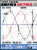
1 - maximum amplitude of the reflected signal; 2 - exit point of the ultrasonic beam; n - finder's arrow
Standard sample No. 2

1 - scale; 2 - block of steel grade 20 GOST 1050-74 in a normalized state with a grain size of 7 points or more according to GOST 5839-65; 3 - screw; 4 - hole for determining the angle of beam entry; 5 - hole for checking the dead zone.
5. PREPARATION FOR CONTROL
5.1. The basis for carrying out initial inspection, as well as repeated inspection after eliminating defects in the weld, is an application signed by the customer. The application, the form of which is given in recommended Appendix 3, is registered in the welding laboratory in a journal (recommended Appendix 4). 5.2. Only welded joints accepted based on the results of external inspection and meeting the requirements of GOST 16037-80 are subject to control. 5.3. It is prohibited to inspect welded joints of pipelines filled with liquid. 5.4. Workstations for performing ultrasonic testing must be prepared in advance. To work in hard-to-reach places and at heights, support personnel must be allocated to help flaw detectors. 5.5. Selecting the sounding method, type of finder, contact fluid, control circuit. 5.5.1. Depending on the thickness of the elements being welded (GOST 16037-80), a sounding method is chosen that allows for control of the cross-section of the entire deposited metal (Table 1). 5.5.2. Distance B, to which the surface of the movement zone of the IC type finder must be prepared on both sides of the weld reinforcement bead, is selected according to table. 1 or in cases of using other types of finders is calculated using the formulas:B 1 = d × tan a -l/2+d+m (1)
When sounded directly
B 2 =2 d × tan a +d+m (2)
When sounded by a direct and once reflected beam
B 3 =3 d × tan a -l/2+d+m (3)
When sounded by a once and twice reflected beam
Table 1
Ultrasonic testing parameters
|
Thickness of welded elements according to GOST 16037-80, mm |
Sounding method*) |
Finder prism angle, degrees. |
Finder operating frequency, MHz |
Finder movement area, mm |
Stripping zone B**, mm |
Limit sensitivity S p (first rejection level), mm 2 |
Area and linear dimensions of the vertical face of the corner reflector |
||
|
area S mm 2 |
width b mm |
height h mm |
|||||||
|
from 6 to 7.5 incl. |
Direct and once reflected beam |
||||||||
|
over 7.5 to 10 incl. |
|||||||||
A diagram explaining the indicated formulas for determining the stripping zone is shown in Fig. 4. 5.5.3. Surfaces at a distance B on both sides of the seam reinforcement must be cleaned of metal splashes, flaking scale, rust, dirt and paint. Cleaned surfaces should be free of dents, irregularities and nicks. A highly correlated surface (corrosion depth greater than 1 mm) must be machined until a flat and smooth surface is obtained. For cleaning, it is recommended to use metal brushes, chisels and grinders with an abrasive wheel. After mechanical treatment of the surface, its roughness should be no more than R z = 40 microns according to GOST 2789-73. 5.5.4. Cleaning the surface and removing contact liquid after testing is not the responsibility of the flaw detector. 5.5.5. After cleaning, the welded joint is marked into sections and numbered so that the location of the defect can be unambiguously determined along the length of the seam according to the diagram shown in Fig. 5 . 5.5.6. To create an acoustic contact, transformer oil is used in accordance with GOST 982-80, glycerin is used in accordance with GOST 6259-75, and liquids developed by the Taganrog Krasny Kotelshchik plant and the Chernivtsi Machine-Building Plant (recommended Appendix 5). At temperatures above 25 ° C or diameters of welded elements less than 300 mm with a vertical arrangement, autoly 6, 10, 12, 18 are used as contact fluids, solid oil - according to GOST 4366-76 or other mineral oils similar to those indicated in viscosity.
Scheme for determining surface cleaning zones near the seam of a welded joint

D - thickness of welded elements, mm; a - input angle, degrees; d - distance from the insertion point to the rear edge of the finder, mm; - half the width of the seam reinforcement bead, mm; B 1 , B 2 , B 3 , - zones of surface cleaning when sounding with a direct, once and twice reflected beam, mm; m =20 mm
Marking the circular welded joint of the pipeline into sections and their numbering

1. The welded joint must be divided into 12 equal sections around the circumference of the elements being welded. 2. The boundaries of the sections are numbered from 1 to 12 in a clockwise direction with the indicated direction of movement of the product in the pipeline. 3. Plots are numbered with two numbers: 1-2, 2-3, etc. 4. The boundary between sections 11-12 and 12-1 should pass through the welder’s mark, perpendicular to the seam.
5.6. The frequency and angle of the finder prism are selected based on the thickness of the elements being welded and the sounding method according to the table. 1. 5.7. Sounding the seams should be done by transversely and longitudinally moving the finder along the prepared in accordance with paragraphs. 5.5.2, 5.5.3, 5.5.5 surface with simultaneous rotation of it at an angle of 3-5 ° in both directions from the direction of transverse movement. The size of the step of movement of the finder should be no more than half the diameter of the piezoelectric plate of the transducer (Table 2). 5.8. Checking basic control parameters. 5.8.1. Before setting up a flaw detector to test a specific product, the following basic control parameters must be checked in accordance with the requirements of GOST 14782-76: finder boom; angle of entry of the ultrasonic beam into the metal; dead zone; extreme sensitivity; resolution. 5.8.2. The finder arm and the angle of entry of the ultrasonic beam are checked at least once per shift. 5.8.3. The finder arrow is determined according to standard sample No. 3 according to GOST 14782-76 and it should not be less than the values specified in the table. 2. 5.8.4. The angle of entry of the ultrasonic beam is determined according to standard sample No. 2 according to GOST 14782-76 and it should not differ from the nominal value by more than ± 1°. The nominal values of the input angle for finders with different prism angles are given in Table 2.
table 2
FINDER PARAMETERS
|
Finder prism angle (b), degrees. |
Operating frequency (f), MHz |
Transducer diameter, mm |
Finder boom, mm |
Input angle (a) of the ultrasonic beam (plexiglass-steel), deg. |
4.0>h/b>0.5,
And the areas S p of the flat bottom of the hole (or segment) and S 1 of the vertical face of the corner reflector are related by the relation:
S p = NS 1, where
N is the coefficient determined from the graph (Fig. 6). 5.8.7. The maximum sensitivity is checked on test samples with artificial reflectors, the area of which is selected from the table. 1 depending on the thickness of the elements being welded and the type of finder selected.
Dependence of coefficientNfrom the cornerabeam input

5.8.8. The material of the test samples must be similar in terms of acoustic properties and surface cleanliness to the product being tested. The test samples must be free of defects (except for artificial reflectors) detected by the pulse echo method. 5.8.9. A reflector of the “hole with a flat bottom” type is made in the test sample in such a way that the center of the reflective surface of the bottom of the hole is located at a depth d equal to the thickness of the elements being welded (Fig. 7). 5.8.10. Test samples with corner or segment reflectors must have the same radius of curvature as the product being tested if the internal diameter of the elements being welded is less than 200 mm. When the internal diameter of the welded elements is 200 mm or more, test samples with plane-parallel surfaces are used (Fig. 8, 9). The method for manufacturing segmental reflectors is given in reference Appendix 6. The corner reflector in the test sample is made using a device from the KOU-2 kit. 5.8.11. The results of testing the maximum sensitivity are considered satisfactory if the signal amplitude from the artificial reflector is at least 30 mm across the CRT screen. 5.8.12. Resolution is checked using standard sample No. 1 according to GOST 14782-76. The resolution is considered satisfactory if the signals from three concentrically located cylindrical reflectors with diameters 15A 7, 20A 7, 30A 7, made in standard sample No. 1 (Fig. 1), are clearly distinguishable on the CRT screen.
Sample with a reflector type: “hole with a flat bottom” for adjusting the sensitivity of the flaw detector

Test sample with an angular reflector for adjusting sensitivity, determining the coordinates of defects and setting the control zone of the flaw detector

Where n is the number of reflections
Test sample with a segmented reflector for adjusting sensitivity, determining the coordinates of defects and setting the control zone of the flaw detector

The length of the test sample is determined by the formula:
L ¢ =(n+1) d × tg a +d+m+25; m=20,
Where n is the number of reflections
5.9. Setting up a flaw detector for inspection. 5.9.1. Connect a finder to the flaw detector with the parameters selected according to the table. 1 in accordance with the thickness of the elements being welded, the acoustic properties of the metal and the geometry of the welded joint. 5.9.2. Prepare the flaw detector for operation in accordance with the requirements of the operating instructions, and then configure it for testing a specific product in the following sequence (basic operations): set the sweep duration; adjust the depth measuring device; set the maximum sensitivity (first rejection level); sensitivity is equalized using a temporary sensitivity adjustment system (TSC); set search sensitivity; set the duration and position of the strobe pulse. 5.9.3. The sweep duration is set in such a way as to ensure the possibility of observing the signal from the most distant reflector on the CRT screen in accordance with the selected control parameters. 5.9.4. The strobe pulse is installed so that its leading edge is located near the probing pulse, and its rear edge is at the end of the CRT screen along the scan line. 5.9.5. Adjust the depth measuring device of the flaw detector according to the operating instructions. If the flaw detector does not have a depth-measuring device, then it is necessary to calibrate the scale of the CRT screen in accordance with the thickness of the product being tested. The method for determining coordinates on the CRT screen scale for the "ECHO" set is given in recommended appendix 7. The method for checking the depth gauge scale of the DUK-66P flaw detector is given in recommended appendix 8. 5.9.6. To set up the depth-measuring device, it is recommended to use test samples with artificial reflectors of the “side drilling” type in the case of testing welded joints with a wall thickness of more than 15 mm (recommended Appendix 8) and samples with segment or corner reflectors for welded joints with a wall thickness of 15 mm or less ( drawings 8 and 9). 5.9.7. Set the maximum sensitivity (first rejection level). The values of the reflector area corresponding to the first rejection level for a specific controlled product are determined according to table. 1. 5.9.8. The flaw detector is adjusted to the first rejection level using the “attenuation” or “sensitivity”, “cut-off”, “power” and VRF regulators so that the height of the echo signal from the artificial reflector is equal to 30 mm, regardless of the control circuit in the absence of noise in the working section of the sweep . 5.9.9. Set the level of operation of the automatic defective alarm system (ADS). 5.9.10. The values of the second rejection level of maximum sensitivity are set higher than the first by 3 dB. 5.9.11. To set the flaw detector to the second rejection level, turn the “weakening” control (for flaw detectors with an attenuator) 3 dB to the left (counterclockwise) or the “sensitivity” control (for flaw detectors without an attenuator) 1 division to the right clockwise with respect to the first rejection level . 5.9.12. Set search sensitivity. The search sensitivity level values are set above the first rejection level by 6 dB. 5.9.13. To adjust the flaw detector to search sensitivity, turn the “attenuation” knob 6 dB to the left (counterclockwise) or the “sensitivity” knob 2 notches to the right (clockwise) relative to the value of the first rejection level. 5.9.14. Set the duration and position of the strobe pulse in accordance with the controlled thickness and method of sounding according to the method outlined in the recommended Appendix 9.
6. CONTROL
6.1. The inspection includes the operations of sounding the weld metal and the heat-affected zone and determining the measured characteristics of defects. 6.2. Sounding of seams is carried out using the method of transverse-longitudinal movement of the finder, set out in paragraph 5.7. The speed of movement of the finder should be no more than 30 mm/s. 6.3. Acoustic contact of the finder with the surface on which it moves is ensured through the contact liquid by lightly pressing the finder. The stability of the acoustic contact is evidenced by a decrease in the amplitude levels of the signals at the trailing edge of the probing pulse, created by the acoustic noise of the finder, compared to their level when the acoustic contact of the finder with the surface of the product deteriorates or is absent. 6.4. Sounding of welded joints is carried out at search sensitivity, and the characteristics of identified defects are determined at the first and second rejection levels. Only those echo signals are analyzed that are observed in the strobe pulse and have a height of at least 30 mm at the search sensitivity. 6.5. During the inspection process, it is necessary to check the setting of the flaw detector to the first rejection level at least twice a shift. 6.6. At the first rejection level, defects are assessed by amplitude, and at the second rejection level, the conditional length, conditional distance between defects and the number of defects are assessed. 6.7. The seams of welded joints sound with direct and once reflected rays on both sides (Fig. 10). When echo signals appear near the trailing or leading edges of the strobe pulse, it is necessary to clarify whether they are a consequence of reflection of the ultrasonic beam from reinforcement or sagging at the root of the seam (Fig. 11). To do this, measure the distances L 1 and L 2 - the position of the finders (I), at which the echo signal from the reflector has the maximum amplitude, and then place the finder on the other side of the seam at the same distances L 1 and L 2 from the reflector - the position of the finders (II). If there are no defects under the surface of the reinforcement bead or at the root of the weld, echo signals will not be observed at the edges of the strobe pulse. If the echo signal is caused by reflection from the reinforcement of the suture, then when it is touched with a tampon moistened with contact fluid, the amplitude of the echo signal will change in time with the touch of the tampon. It must be taken into account that acceptable undercuts can also cause false echoes. In this case, it is recommended to clean the area of the weld that gives the reflection flush with the surface of the base metal and then re-inspect. If there are no defects, echo signals will not be observed at the edges of the strobe pulse.Patterns for sounding seams with symmetrical cutting of edges


A - with a bevel of two edges, b - with a curved bevel of two edges
Scheme for decoding false echoes

A - from sagging at the root of the seam; b - from the seam reinforcement roller
6.8. Butt joints with a bevel of one edge with a wall thickness of more than 18 mm are recommended, in addition to sounding on both sides according to the method for symmetrical cutting, to additionally sound with finders with a prism angle of 54° (53°) on the side of the edge without the bevel (Fig. 12). In this case, the searcher movement zone and the stripping zone are calculated using the formulas in clause 5.5.2, and the maximum sensitivity (the first rejection level) is set equal to 6 mm 2. 6.9. When half the width of the seam reinforcement l /2 does not exceed the distance L 1 from the front edge of the finder to the projection of the supposed defect at the root of the weld on the surface of the welded joint, sounding the lower part of the weld is performed with a direct beam (Fig. 13a), and when l /2 exceeds L 1 the lower part of the seam is sounded by a doubly reflected beam (Fig. 13b). 6.10. To compare the values of quantities l /2 and L 1 it is recommended to experimentally determine the distance L 1 (Fig. 14). The finder is installed at the end of the tested pipe or test sample used to adjust the flaw detector to the first rejection level. By moving the finder perpendicular to the end, fix the position of the finder at which the echo signal from the lower corner will be maximum, and then measure the distance L 1. 6.11. With unilateral access to the seam, it is sounded only on one side (Fig. 15). If the thickness of the welded elements is no more than 18 mm, the seam should be additionally sounded with finders with a prism angle of 54° (53°) according to the method described in clause 6.8. In the conclusion and in the control log, an appropriate entry must be made that the sounding was carried out only on one side of the seam.
Patterns for sounding seams with asymmetrical cutting of edges

A - with a bevel of one edge; b - with a curved bevel of one edge; c - with a stepped bevel of one edge; a 2 > a 1 ; a 2 =54°(53°)
Scheme of sounding the lower part of the seam.

A - size l /2 less than L 1 by such an amount that the searcher movement area equal to L 1 - l /2 allows you to fully sound the root of the seam with a direct beam; b - area of movement of the finder equal to L 1 - l /2 allows you to sound only part of the root of the seam with a direct beam, and the rest with a doubly reflected beam
Scheme of experimental determination of distance

Scheme of sounding a seam with unilateral access

Scheme of sounding a seam with different wall thicknesses of joined elements

6.12. If the joined elements have different thicknesses without bevelling a wall of greater thickness, then sounding should be performed in accordance with clause 6.7. When a signal appears near the trailing edge of the strobe pulse, it is necessary to take into account that when the finder is located on the side of the thicker wall of the element at a distance L 1 = tg a from the weld axis, the signal is from the lower corner of the wall and the signal from the defect in the root of the seam (Fig. 16) can be observed as a single signal. To determine from which reflector the signal is observed, it is necessary to install the finder on the side of the thinner wall thickness of the element at a distance L 1 from the axis of the seam. In this case, if the signal is not observed near the trailing edge of the strobe pulse, there is no defect, but if the signal is observed, then a defect is detected in the root of the weld. 6.13. If the joined elements have different thicknesses with a bevel of a wall of greater thickness, then on the side of the smaller thickness the sounding is performed according to clause 6.7, and on the side of the greater wall thickness of the element - according to the diagrams shown in Fig. 17, 18. The thickness of the walls of the joined pipes and the actual boundary (length) of the bevel are determined with a direct finder in accordance with the recommended Appendix 10. 6.14. The main measured characteristics of identified defects are: amplitude of the echo signal from the defect; defect coordinates; conditional length of the defect; conditional distance between defects; the number of defects in any section of a 100 mm long seam. 6.15. The amplitude in dB of the echo signal from the defect is determined by the readings of the “attenuation” regulator (attenuator).
Schemes for sounding seams with a direct and once reflected beam from the side of an element of greater thickness

Intervals of movement of the finder when sounding a seam: a - with a straight beam from L "to L", where L "= l /2 +n; L "= d × tg a; b - once reflected beam from to , where =5(d 1 - d)+10+ d 1 × tg a, =2 d 1 × tg a + l /2 ; L =5(d 1 - d).
Scheme of sounding seams with a doubly reflected beam from the side of an element of greater thickness

The interval of movement of the finder from to , where =2 d 1 × tg a + l /2 ; =(2 d 1 + d) tg a
6.16. The coordinates of the defect - the distance L from the beam entry point to the projection of the defect onto the surface of the welded joint and the depth H - are determined in accordance with the requirements of the operating instructions for flaw detectors (Figure 19) 6.17. The coordinates of the defect are determined at the maximum amplitude of the reflected signal. If the echo signal goes beyond the screen, then the “attenuation” or “sensitivity” controls reduce its amplitude so that the maximum signal is in the range from 30 to 40 mm. 6.18. The conditional length of the defect and the conditional distance between defects are determined according to GOST 14782-76. When measuring these characteristics, the extreme positions of the finder should be considered those at which the amplitude of the echo signal from the defect is 0.2 of the vertical size of the working field of the CRT screen.
7. PROCESSING AND REGISTRATION OF CONTROL RESULTS
7.1. Assessment of the quality of seams of welded joints. 7.1.1. The measured characteristics of defects in the seams of welded joints are assessed in accordance with the requirements of this standard and the current regulatory and technical documentation. The maximum permissible values of the measured characteristics of defects, established taking into account the requirements of SNiP III -31-78, are given in table. 3. 7.1.2. The quality of the seams of welded joints is assessed based on the results of control according to the principle: “pass” - “fail”. The term “passable” evaluates the seams of welded joints without defects or with defects, the measured characteristics of which do not exceed the standards specified in Table. 3. The term “unfit” is used to evaluate the seams of welded joints if defects are found in them, the measured characteristics of which exceed the standards specified in the table. 3.Determination of defect coordinates

Table 3
MAXIMUM ALLOWABLE VALUES OF MEASURED CHARACTERISTICS AND NUMBER OF DEFECTS IN WELDED JOINTS
|
Nominal thickness of welded elements, mm |
Amplitude estimation |
Evaluation by conditional length, conditional distance between defects and number of defects |
Conditional length (mm) of a defect located at depth, mm |
The number of defects acceptable according to the measured characteristics on any 100 mm of seam length |
Total conventional length (mm) of permissible defects for any 100 mm of seam length located at a depth, mm |
||
|
from 6.0 to 20.0 incl. |
First rejection level |
Second rejection level |
|||||
|
over 20.0 to 40.0 incl. |
|||||||
|
over 40.0 to 50.0 incl. |
|||||||
ANNEX 1
Operating frequencies, MHz
Attenuator dynamic range, dB
Maximum sounding depth (for steel), mm
Availability of depth gauge
Dimensions of the working part of the CRT screen, mm
Operating temperature range, ° K (° C).
Dimensions, mm
Weight, kg
Supply voltage, V
Power type
0,80; 1,80; 2,50; 5,00
70 diameter
278-303 (from +5 to +30)
220 × 335 × 423
0,60; 1,80; 2,50; 5,00
125; 2,50; 5,00; 10,00
(from minus 10 to +40)
260×160×425
260 × 170 × 435
220, 127, 36, 24
0,60; 1,25; 2,50; 5,00
50 (in steps of 2dB)
278-323 (from +5 to +50)
345 × 195 × 470
40 (smooth)
1,25; 2,50; 5,00; 10,00
263-323 (from minus 10 to +50)
130 × 255 × 295
500 (for aluminum)
278-424 (from +5 to +50)
520 × 490 × 210
258-313 (from minus 15 to +40)
140 × 240 × 397
APPENDIX 2
METHOD FOR DETERMINING THE LINEARITY OF THE SPECIALIZED "ECHO" KIT
The linearity of the scan line is determined as follows: 1. Connect a direct finder to socket 1 of the flaw detector. 2. The toggle switch for the “type of work” switch is set to position 1. 3. The attenuator switches “fine” and “coarse” are set to position “0”. 4. If necessary, use the “noise cut-off” control to remove noise from the scan line. 5. Use the " " knob to remove the strobe pulse from the screen. 6. The “rough scan” switch is set to position “5”. 7. The “sweep smoothly” regulator is set to the extreme right position. 8. Install the finder on the surface of standard sample No. 2 GOST 14782-76. 9. Achieve the maximum number of reflected bottom signals on the screen so that they are distributed along the entire scan line. 10. Measure the distance between the leading edges of the reflected signals using a scale on the CRT screen. 11. Linearity is considered satisfactory if the distances between the pulses do not differ from each other by more than 10%. 12. Linearity is checked in the same way for the remaining sweep ranges.APPENDIX 3
Name of the organization issuing the application APPLICATION No. 1. The application was submitted by __________________________________________________________ (initials and surname) 2. Name of the object ___________________________________________________ 3. Name and brief characteristics of the controlled product ____________ ________________________________________________________________________ __________________________________________________________________________ |
APPENDIX 4
APPLICATION REGISTRATION JOURNAL FORM
APPENDIX 5
CONTACT LIQUIDS
Contact fluid of the Taganrog plant "Krasny Kotelshchik"
The easily washable inhibitor contact fluid has the following composition: water, l.................................................... ........................................................ ........................... 8 sodium nitrite (technical), kg................ ........................................................ ..... 1.6 starch (potato), kg.................................... ........................................... 0.24 glycerin (technical) , kg........................................ ........................... 0.45 soda ash (technical), kg......... ........................................... 0.048
Cooking method
Soda and sodium nitrite are dissolved in 5 liters of cold water and boiled in a clean container. Starch is dissolved in 3 liters of cold water and poured into a boiling solution of sodium nitrite and soda. The solution is boiled for 3-4 minutes, after which glycerin is poured into it, then the solution is cooled. Contact liquid is used at temperatures from +3 to +38 º C.
Contact fluid of Chernivtsi Machinery Plant
The contact liquid is an aqueous solution of polyacrylamide and sodium nitrite in the following ratio: polyacrylamide in % ................................... ........................................................ .......... from 0.8 to 2 sodium nitrite in% .................................... ........................................................ ............... from 0.4 to 1% water .............................. ........................................................ ................................ from 98.8 to 97
Cooking method
500 g of technical (8%) polyacrylamide and 1.3 liters of water are loaded into a steel tank with a capacity of 3 liters, equipped with a stirrer at a speed of 800-900 rpm, and stirred for 10-15 minutes. until a homogeneous solution of sodium nitrite is obtained. The appropriate amount of polyacrylamide, sodium nitrite solution and water is loaded into the hopper. Then the motor and the contents of the hopper are turned on for 5-10 minutes. pumped repeatedly until a homogeneous mass is obtained. When using a pump with a capacity of 12.5 l/min. An electric motor with a power of 1 kW is used.
APPENDIX 6
Information
METHOD FOR MANUFACTURING SEGMENTAL REFLECTORS
Segmental reflectors are made on the surface of the test sample by milling on a jig boring machine according to the scheme (Fig. 1). The diameter of the cutter is selected depending on the required area of the segment reflector. The milling depth H is selected according to the graphs (Fig. 2, 3). The inclination angle α of the cutter is set equal to the angle of input of ultrasonic vibrations. It is allowed to manufacture segmental reflectors on milling machines. The milling depth H is measured with an indicator with a needle bore gauge.Method for manufacturing segment reflectors

Graph of the dependence of the milling depth "H" on the segment area "S" for finders with different prism angles (cutter diameter 3 mm)

Graph of the dependence of the milling depth "H" on the area "S" for finders with different prism angles (cutter diameter 6 mm)

APPENDIX 7
METHOD FOR DETERMINING THE COORDINATES OF DEFECTS WITH THE "ECHO" SET WHEN INSPECTION OF WELDED JOINTS SEAMS
1. General instructions
1.1. The coordinates "H" and "L" are determined directly from the scale of the CRT screen. 1.2. To determine coordinates on a scale, perform the following operations: select the working sweep range; the position and duration of the strobe pulse are set in accordance with the seam control zone of the welded joint and the scale is calibrated in relation to the thickness of the elements being welded, and the scale factors KH and KL are calculated. 1.3. The ECHO set is configured using a test sample, which is used to adjust the sensitivity during testing. 1.4. For convenience of calculations, the value of the small horizontal scale division is taken to be 0.2. 1.5. The "Y" regulator aligns the scan line with the lower horizontal scale line, and the "X" regulator aligns the maximum amplitude of the probing pulse with the first left vertical scale line of the screen. 1.6. Set the “coarse sweep” switch to position “5” and the “ ” knob to the extreme right position. 1.7. Use the " " regulator to set the leading edge of the strobe pulse near the trailing edge of the probing pulse (PS), and use the " " regulator to set the duration of the strobe pulse such that its trailing edge is located at the end of the scale.
2. Methodology for determining the coordinates of defects when sounding the seams of welded joints with a direct beam
2.1. In accordance with the thickness of 6 welded elements according to table. 1 determine the scale factor K N.
Table 1
2.2. In accordance with the thickness δ "(part of the thickness) of the seam of the welded joint, control of which is possible with a direct beam, equal to the distance from the center of reflector 1 (of the “side drilling” type) to the bottom of the test sample (Drawing 1), the number of divisions that is necessary is determined by the formula install between the leading edges of signals (1) and (2). 2.4. The “coarse sweep”, “” and “” regulators achieve a distance between the leading edges of the maximum amplitudes of signals (2) and (1) equal to N large divisions, using the method of successive approximation (in the example considered in Figure 1 N = 4 ,4).An example of scale graduation when sounding the seams of welded joints with a direct beam

2.5. Using the " " regulator, combine the leading edge of the strobe pulse with the position of the leading edge of the signal (1). 2.6. Use the " " regulator to align the trailing edge of the strobe pulse with the position of the leading edge of the signal (2). 2.7. To determine the coordinates of the defect, set the maximum amplitude of the signal from the reflector detected in the control zone (for example, signal (3) from reflector 3, Fig. 1). Then count the number of divisions N i from the trailing edge of the strobe pulse to the leading edge of the signal from the defect in the control zone and determine the depth (H) of the defect using the formula:
H= δ -N i K N;
In the example of hell. 1 N i = 2.6. 2.8. Distance L is determined by the formula:
3. Methodology for determining the coordinates of defects when sounding the seams of welded joints with a direct and once reflected beam
3.1. In accordance with the thickness δ of the welded elements according to table. 2 determine the scale factor K H .
table 2
3.2. The number of divisions N p is determined, which is set between the positions of the leading edges of signals from reflectors 2 and 4 when sounded by a single reflected beam (Fig. 2) according to the formula:N p = δ / K H .
3.3. The number of divisions is determined, which is set between the positions of the leading edges of signals (1) and (2) from reflectors 1 and 2 when sounded by a direct beam (Fig. 2) according to the formula:
N l = δ "/ K H.
3.4. By moving the finder along the test sample, they achieve the maximum amplitude of the signal (4) from the reflector 4 (Fig. 2), located at the maximum distance from the beam entry point when sounded by a single reflected beam. 3.5. Set the "scan coarse" switch and the "" regulator signal (4) between 8 and 9 large divisions of the horizontal scale. 3.6. Using the " " and " " controls, using the method of successive approximations, the leading edge of the maximum signal amplitude (2) from reflector 2 is aligned with the middle of the scale, and the leading edge of the maximum signal amplitude (4) from reflector 4 is located at a distance equal to N n divisions (clause 3.2.) from the middle of the scale to the right. 3.7. Using the " " regulator, set the leading edge of the strobe pulse at a distance equal to N l divisions (clause 3.3.) from the middle of the scale to the left, corresponding to the position of the leading edge of the maximum amplitude of the signal (1) from reflector 1. 3.8. Use the " " regulator to align the trailing edge of the strobe pulse with the position of the leading edge of the maximum amplitude of the signal (4) from reflector 4 (clause 3.6.).
An example of scale graduation when sounding the seams of welded joints with a direct and once reflected beam

3.9. All signals detected within the duration of the set strobe pulse from its leading edge to the middle of the scale are considered to be detected by a direct beam, and from the middle of the scale to the trailing edge - by a single reflected beam. 3.10. Depths (N l, N p) of detected defects in the area of direct beam sounding are determined by the formula:
N l = δ - N l i K N;
Where N l i is the number of scale divisions, counted from the middle to the leading edge of the signal from the defect, and in the sound zone of a single reflected beam is determined by the formula:
N p = δ - N p i K N;
Where N p i is the number of scale divisions, counted from the trailing edge of the strobe pulse to the leading edge of the signal from the defect. 3.11. Determine the distance L l in the sounding area with a direct beam using the formula:
L l =N l · tg α ;
A once reflected beam according to the formula:
L p =(2 δ -Н p) · tg α ;
3.12. The method for setting up the "ECHO" kit to determine the coordinates of defects while simultaneously sounding the seams of welded joints with single- and double-reflected beams is similar to the above. In this case, the coordinates H and L are determined by the formulas:
N= N l i K N;
Where KH increases 3 times compared to the values in the table. 1.
L p = [(n +1) δ -Н p ] · tg α .
APPENDIX 8
METHOD FOR CHECKING THE ERROR OF THE DEPTH GAUGE OF THE DUK-66P FEFECTOSCOPE
1.1. Set the scale selected in accordance with the operating frequency and angle of the finder prism. 1.2. The finder is moved along the surface of the test sample and, upon receiving a signal of maximum amplitude from each of the three holes (see drawing), the coordinates H and L are measured using a depth-measuring device. 1.3. The coordinates determined by the depth gauge are compared with the coordinates measured by metric means directly on the sample. 1.4. If the permissible error (according to the passport for the flaw detector) obtained from the results of the above comparison is exceeded, it is recommended to send the device for verification.Test sample with "side drilling" type reflectors for checking and adjusting the depth gauge scale of a flaw detector type DUK-66P

APPENDIX 9
METHOD FOR SETTING THE DURATION AND POSITION OF THE STROBE PULSE
1.1. The duration and position of the strobe pulse are set in accordance with the selected sounding method (direct, once or twice reflected beam). 1.2. The flaw detector is adjusted using a test sample with reflectors used to set the maximum sensitivity (the first rejection level). 1.3. In flaw detectors UDM-1M, UDM-3, DUK-66P, DUK-66PM, with the exception of the “ECHO” set, the technique for setting the strobe pulse is similar. 1.4. The method for setting the duration and position of the strobe pulse for the "ECHO" set is directly related to the method for determining coordinates and is outlined in recommended Appendix 7. 1.5. When sounding the seam of a welded joint with a direct and single-reflected beam, the leading edge of the strobe pulse is set along the leading edge of the signal with maximum amplitude reflected from the lower reflector (corner or segment), and the trailing edge of the strobe pulse is set along the trailing edge of the signal with maximum amplitude reflected from the upper reflector - corner or segment (Fig. 1). With this setting, echoes appearing at the beginning of the strobe pulse indicate the presence of defects in the lower part of the seam, and echoes at the end of the strobe pulse indicate the presence of defects in the upper part of the seam.Scheme for determining the duration and position of a strobe pulse when sounding a seam with a direct and once reflected beam

L "is calculated depending on δ, α and the sound pattern using the formula: L "=(n +1) d × tg a + d + m +25, where n is the number of reflections
1.6. When sounding the seam of a welded joint with a double and once reflected beam, the leading edge of the strobe pulse is set along the leading edge of the signal with maximum amplitude reflected from the upper reflector, and the trailing edge of the strobe pulse is set along the trailing edge of the maximum signal with maximum amplitude reflected from the lower reflector . With this setting, echo signals at the beginning of the strobe pulse indicate the presence of defects in the upper part of the seam, and echo signals at the end of the strobe pulse indicate the presence of defects in the lower part of the seam (Fig. 2) 1.7. The position of the strobe pulse is set using the “X offset” regulator symmetrically relative to the middle of the CRT screen scale for all flaw detectors with the exception of the “ECHO” set.
Scheme for determining the duration and position of a strobe pulse when sounding a seam with a single and double reflected beam

APPENDIX 10
DETERMINATION OF THE WALL THICKNESS OF WELDED ELEMENTS AND THE ACTUAL BOUNDARY (LENGTH) OF THE BEvel USING A DIRECT FINDER
1.1. The finder is installed on the surface of the welded elements, previously prepared for inspection on both sides of the seam and covered with a contact liquid, at a distance of at least 40 mm from the line of transition of the seam into the base metal. If the diameter of the welded elements is less than 300 mm, the specified surface is cleaned until a flat plane is obtained with a width greater than the diameter of the straight finder (see drawing). 1.2. Using a depth-measuring device configured for measurement with a direct finder according to the instructions for the flaw detector, the thickness of the walls of the elements being welded is determined. 1.3. To determine the actual boundary (length L ck) of the bevel, the finder is moved along the surface of the element having a large thickness towards the seam until a sharp increase in the distance between the probing and the nearest reflected pulses appears in comparison with the distance between the remaining multiple reflected signals. Having marked the position of the finder found in this way (see the explanatory diagram in the drawing), the distance L ck from the center line of the seam to the position of the mark on the surface of the element is measured with a ruler.Scheme of sounding the walls of welded elements with a direct finder to determine their thickness and bevel length

SI - probing pulse; 1,2,3... signals reflected from the opposite side of the wall of the elements being welded
APPENDIX 11
JOURNAL OF ULTRASONIC TESTING
|
Conclusion number and date of issue |
Date of control |
Name of the control object and its address |
Scope of control |
Characteristics of the welded joint |
Control parameters |
Control results |
Assessing the seam quality of a welded joint |
Information about re-inspection |
Last name of flaw detector |
Signature of the flaw detector |
Note |
||||||||||
|
Connection type |
Index (number) of the seam according to the drawing |
Diameter and thickness of welded elements, mm |
Steel grade |
Welding method |
Flaw detector type and number |
Operating frequency, MHz |
Finder prism type and goal, deg |
Area of maximum permissible equivalent defect |
Weld joint section number |
Brief description of detected defects |
Number of detected defects per 100 mm of seam length |
Conditional length of defects per 100 mm of seam length, mm |
|||||||||
APPENDIX 12
|
(Object name) |
(name of the organization that carried out the control - |
||
| Line no. |
trust installation department, laboratory) |
||
CONCLUSION No.___ Drawing (form, wiring diagram) No. _______________________________________________________________________________ Last name, first name, patronymic and number of the welder's mark _____________________________________________________________________ Type of flaw detector and its serial number ____________________________________________________________________________ Head of the laboratory ________________________________________________________________ signature (last name, first name, patronymic) Flaw detector for ultrasonic testing ___________________________________ signature (last name, first name, patronymic) |
|||
APPENDIX 13
DEFECTOGRAM No. 6 OF WELDED JOINT No. 30 ENTRY No. 21 IN THE ULTRASONIC TESTING JOURNAL
(filling example)

Note: the "+" arrow indicates the direction of movement of the product away from us perpendicular to the drawing plane
| 1. Purpose of the method. 2 2. Requirements for flaw detectors and the ultrasonic testing area. 2 3. Safety requirements. 3 4. Requirements for equipment and materials.. 4 5. Preparation for control.. 7 6. Conducting control. 14 7. Processing and registration of control results. 19 Appendix 1 Recommended flaw detectors and their main technical characteristics. 21 Appendix 2 Methodology for determining the linearity of the scan of a specialized "echo" set. 22 Appendix 3 Application for ultrasonic testing of welded joints. 22 Appendix 4 Application log form. 23 Appendix 5 Contact liquids. 23 Appendix 6 Method of manufacturing segmented reflectors. 23 Appendix 7 Methodology for determining the coordinates of defects using the “echo” set when inspecting the seams of welded joints. 25 Appendix 8 Methodology for checking the error of the depth gauge of the duk-66p flaw detector. 28 Appendix 9 Methodology for establishing the duration and position of the strobe pulse. 29 Appendix 10 Determination of the wall thickness of the elements being welded and the actual boundary (length) of the bevel using a straight finder.. 30 Appendix 11 Ultrasonic testing journal. 32 Appendix 12 Conclusion on checking the quality of seams of butt welded joints of pipelines using the ultrasonic method. 32 Appendix 13 Defectogram No. 6 of welded joint No. 30, entry No. 21 in the ultrasonic testing log. 33 |
Ultrasonic testing is carried out on process pipelines (to the extent according to the category of the pipeline), pipelines of heating networks (depending on the conditions of laying the pipeline and the requirements of the operating organization), fire pipelines, gas pipelines, steam pipelines, drill pipe and pump-compressor pipe, etc.
Ultrasonic testing pipe inspection is a pipeline diagnostics for the presence of internal defects. Both the pipe body itself and the weld seam can be inspected. This type of flaw detection can be carried out both in a specially equipped laboratory on the territory of our enterprise (if the dimensions of the product do not exceed 2000 mm in length and 500 mm in diameter and the weight of the product does not exceed 150 kg), and at the actual location of the object.
If the pipeline is operational, ultrasonic testing is carried out after drainage (removal) of the transported medium. Ultrasonic testing is possible without stopping the technological process, without stopping production (unlike X-ray testing).
Ultrasonic testing must be carried out not only when putting pipelines into operation, during the pipe certification procedure, but also on a regular basis in order to prevent premature wear of pipes and the occurrence of emergency situations.
The procedure for ultrasonic flaw detection of pipelines consists of the following activities:
preparing welded joints for inspection (cleaning). Carried out by the customer or by the laboratory by agreement.
weld marking
direct inspection of the pipeline - inspection of welds or continuous inspection of the pipeline metal, thickness gauging if necessary.
marking defective areas if repairs are possible
drawing up a pipeline diagram and conclusions based on inspection results
As you have already seen, ultrasonic inspection of pipes is a very effective flaw detection method. In addition, this type of control has also proven itself to be the most accurate, efficient, low-cost and safe for humans.
Contact us and we will organize for you the full range of work on ultrasonic inspection of pipelines, identify weak points of objects, existing defects, provide complete information about their size and location relative to the surface of the product, examine welds and connections also in order to control their quality. It is through such checks that you ensure long-term uninterrupted, and most importantly, safe operation of the equipment.
In construction, pipes with Ø from 28 to 1420 mm with a wall thickness from 3 to 30 mm are used. The entire range of diameters according to flaw detection can be divided into 3 groups:
- Ø from 28 to 100 mm and H from 3 to 7 mm
- Ø from 108 to 920 mm and H from 4 to 25 mm
- Ø from 1020 to 1420 mm and H from 12 to 30 mm
According to studies that were carried out at MSTU. N.E. Bauman recently, in the process of developing methods for ultrasonic testing of welded pipe joints, one should take into account such a very important factor as the anisotropy of the elastic characteristics of the pipe material.
Anisotropy of pipe steel, its features
Anisotropy- this is the difference in the properties of a medium (for example, physical: thermal conductivity, elasticity, electrical conductivity, etc.) in different directions within a given medium.
In the process of ultrasonic testing of welded joints of main gas pipelines assembled from pipes of domestic and foreign production, the omission of serious root defects, inaccurate assessment of their coordinates, and a significant level of acoustic noise were discovered.
It turned out that if optimal control parameters are observed and during its implementation, the main reason for missing a defect is the presence of significant anisotropy in the elastic properties of the base material. It affects the speed, attenuation and deviation from straightness of the ultrasonic beam.
During the sounding of metal, more than 200 pieces of pipes according to the scheme shown in Fig. 1, it turned out that the standard deviation of the wave speed with this direction of motion and polarization is equal to 2 m/s (for transverse waves). Deviations of velocities from the table values of 100 m/s or more are not random and are probably associated with the production technology of rolled products and pipes. Such deviations have a strong influence on the propagation of polarized waves. In addition to the indicated anisotropy, inhomogeneity of the speed of sound across the thickness of the pipe wall was also discovered.
Rice. 1. Designations of deposits in the pipe metal: X, Y, Z. - directions of ultrasound propagation: x. y.z: - polarization directions; Y - rolling direction: Z - perpendicular to the plane of the pipe
The structure of rolled sheets is layered, consisting of metal fibers and other inclusions elongated during deformation. In addition, due to the effect of the thermomechanical rolling cycle on the metal, sections of the sheet that are uneven in thickness are subject to various deformations. These features cause the speed of sound to additionally depend on the depth of the sound layer.
Features of control of welded seams of pipes of various diameters
Pipes Ø from 28 to 100 mm
A distinctive feature of welded seams of pipes Ø from 28 to 100 mm with H from 3 to 7 mm is the occurrence of sagging inside the pipe. This causes false echo signals from them to appear on the screen of the flaw detector during testing with a direct beam, which coincide in time with the echo signals reflected from the root defects found by a single reflected beam. Due to the fact that the effective width of the beam is comparable to the thickness of the pipe wall, it is extremely difficult to identify the reflector by the location of the finder relative to the reinforcement roller. There is also an uncontrolled zone in the center of the seam due to the large width of the seam bead. All this is the reason for the low probability (10-12%) of detecting unacceptable volumetric defects, although unacceptable planar defects are detected much better (~ 85%). The main characteristics of sagging - depth, width and angle of contact with the surface of the object - are random variables for this standard size of pipe; the average values are respectively 2.7 mm; 6.5 mm and 56°30".
Rolled steel behaves as an anisotropic and inhomogeneous medium with rather complex dependences of the velocities of elastic waves on the direction of polarization and sounding. The speed of sound changes approximately symmetrically with respect to the middle of the sheet section, and in the region of this middle the transverse wave speed can greatly (up to 10%) decrease compared to the surrounding areas. The shear wave speed in the controlled objects varies in the range from 3070 to 3420 m/s. At a depth of up to 3 mm from the surface of the rolled product, the speed of the transverse wave may increase slightly (up to 1%).
Noise immunity of control increases significantly in the case of using inclined separate-combined probes of the RSN type (Fig. 2), which are called chordal. They were designed at MSTU. N.E. Bauman. A special feature of the inspection is that there is no need for cross scanning when searching for defects. It is performed only along the perimeter of the pipe at the moment the front face of the converter is pressed against the seam.
Rice. 2. Inclined chord RSN-PEP: 1 - emitter: 2 - receiver
Pipes Ø from 108 to 920 mm
Pipes with Ø from 108 to 920 mm with H from 4 to 25 mm are also connected by one-sided welding without back welding. Until recently, the control of these connections was carried out using combined probes according to a method developed for pipes with Ø from 28 to 100 mm. But such a control technique requires the presence of a fairly large zone of coincidence (zone of uncertainty). This significantly reduces the accuracy of connection quality assessment. In addition, combined probes are characterized by a high level of reverberation noise, which makes it difficult to decipher signals, as well as uneven sensitivity, which cannot always be compensated by available means. The use of chordal separate-combined probes for the purpose of monitoring this standard size of welded joints is impractical, since due to the limited values of the input angles of ultrasonic vibrations from the surface of the welded joint, the dimensions of the transducers increase significantly, and the area of acoustic contact becomes larger.
At MSTU. N. E. Bauman created inclined probes with leveled sensitivity to perform inspection of welded joints with a diameter of 100 mm or more. Sensitivity equalization ensures that the rotation angle 2 is selected in such a way that the upper part and middle of the seam are sounded by the central once reflected beam, and the lower part by direct peripheral rays that fall on the defect at an angle Y from the central one. In Fig. Figure 3 shows a graph of the dependence of the angle of introduction of the transverse wave on the angle of rotation and opening of the directional pattern Y. In such probes, the incident and reflected waves from the defect are horizontally polarized (SH-wave).
Rice. 3. Changing the input angle alpha, within the limit of half the opening angle of the RSN-PEP radiation pattern, depending on the rotation angle delta.
It is clear from the graphs that when testing objects with a wall thickness of 25 mm, the uneven sensitivity of the RS-probe reaches 5 dB, while for a combined probe it can reach 25 dB. RS-PEP is characterized by an increased signal-to-interference level and, therefore, increased absolute sensitivity. For example, the RS-PEP easily detects a defect with an area of 0.5 mm2 during the inspection of a welded joint 10 mm thick with both direct and once reflected beams with a useful signal/interference ratio of 10 dB. The procedure for performing control with probe data is the same as for a combined probe.
Pipes Ø from 1020 to 1420 mm
Welded joints of pipes Ø from 1020 to 1420 mm with H from 12 to 30 mm are performed by double-sided welding or with back welding of the seam bead. In seams that are made by double-sided welding, usually, false signals from the trailing edge of the reinforcement roller do not cause as much interference as in single-sided seams. Their amplitude is not so great due to the smoother contours of the roller. In addition, they are further along the scan. For this reason, this is the most suitable pipe size for flaw detection. But the results of research conducted at MSTU named after. N. E. Bauman show that the metal of these pipes is characterized by the greatest anisotropy. To reduce the effect of anisotropy on defect detection, a 2.5 MHz probe should be used with a prism angle of 45°, rather than 50°, as specified in most regulatory documents. The highest control accuracy was achieved using probes of the RSM-N12 type. Unlike the methodology compiled for pipes with Ø from 28 to 100 mm, there is no zone of uncertainty when monitoring these connections. The rest of the control method is similar. When using an RS-PET, it is also recommended to adjust the scanning speed and sensitivity for vertical drilling. The scanning speed and sensitivity of inclined combined probes should be adjusted using corner reflectors of the appropriate size.
When inspecting welds, it must be remembered that in the heat-affected zone there are metal delaminations, which make it difficult to determine the coordinates of the defect. The area in which the defect was found by an inclined probe must be additionally checked by a direct probe in order to clarify the nature of the defect and identify the exact value of the depth of the defect.
In the nuclear, petrochemical and nuclear power industries, clad steels are often used in the manufacture of pipelines, apparatus and vessels. For cladding the inner wall of these structures, austenitic steels are used, which are applied by surfacing, rolling or explosion in a layer of 5 to 15 mm.
The process of monitoring these welded joints involves analyzing the continuity of the pearlite part of the weld, as well as the fusion zone with restorative anti-corrosion surfacing. In this case, the continuity of the body of the surfacing itself is not controlled.
But due to the difference in the acoustic characteristics of the base metal and austenitic steel, echo signals appear from the interface during ultrasonic testing, preventing the detection of defects, for example, cladding delaminations and sub-cladding cracks. In addition, the presence of cladding and its characteristics have a significant impact on the parameters of the acoustic path of the probe.
For this reason, standard technological solutions are ineffective in inspecting thick-walled welds of clad pipelines.
After many years of research, scientists have figured out the main features of the acoustic tract. Recommendations were received for optimizing its characteristics and a technology for performing ultrasonic analysis of welds with austenitic cladding was developed.
In particular, scientists have found that when a beam of ultrasonic waves is reflected from the boundary of pearlite-austenitic cladding, the radiation pattern almost does not change in the case of rolling cladding and changes significantly in the case of surfacing cladding. Its width increases significantly, and within the main lobe there are oscillations of 15-20 dB, depending on the surfacing method. There is a significant movement of the reflection exit point from the beam cladding boundary compared to its location, and the velocity of the shear waves in the transition zone also changes.
When developing technology for monitoring welded joints of clad pipelines, all this was taken into account. This technology provides for a preliminary mandatory determination of the thickness of the pearlite part (the depth of penetration of the anti-corrosion surfacing).
For more accurate detection of planar defects (lack of fusion and cracks), it is better to use a probe with an input angle of 45° and a frequency of 4 MHz. More accurate detection of vertically oriented defects at an input angle of 45°, in contrast to angles of 60 and 70°, is explained by the fact that during sounding of the latter, the angle at which the beam meets the defect is close to the third critical angle, at which the transverse wave reflection coefficient is minimal.
When the pipe is sounded outside at a frequency of 2 MHz, echo signals from defects are screened by an intense and long-lasting noise signal. The resistance to interference of the probe at a frequency of 4 MHz is on average 12 dB higher. For this reason, the useful signal from a defect located in close proximity to the deposit boundary will be better read against the background of noise. And vice versa, when sounding the pipe from the inside through the surfacing, better resistance to interference will be provided by a probe at a frequency of 2 MHz.
The technology for monitoring pipeline welds with surfacing is regulated by Gosatomnadzor document RFPNAEG-7-030-91.