Making plastic cases for devices with your own hands. Simple manufacture of an enclosure for amateur radio devices. DIY iMac


Hi all! Many radio amateurs, after they have done their next craft, face a dilemma - where to “shove” all this, and so that later people would not be ashamed to show it. Well, with cases, let's say at the present time, it's not so a big problem. Now you can find many ready-made cases on sale, or use suitable cases for your designs from any radio equipment that has failed and disassembled into parts, also use building materials in your crafts, or whatever comes to hand.
But to give, so to speak, a “presentation” of its design or to please the eye, at home, is the problem of more than one radio amateur.
I will try to briefly describe here how I make front panels for my crafts at home.
To design and render the front panel, I use free program FrontDesigner_3.0 . The program is very simple to use, everything becomes clear immediately, in the process of working with it. It has a big library sprites (drawings), it is something like Sprint Layout 6.0.
Which are now the most accessible for a radio amateur sheet materials- this is plexiglass, plastic, plywood, metal, paper, various decorative films and so on. Everyone chooses for himself what is more suitable for him in terms of aesthetic, material and other conditions.
How I make my panels:
1 - I pre-think and put in place what I will have installed on the front panel in my design. Since the front panel is a kind of “sandwich” (plexiglass - paper - metal or plastic) and this sandwich needs to be fastened together somehow, I use the principle - how will it all be held and in what places. If mounting screws are not provided on the panel, then only nuts for fastening connectors, variable resistances, switches and other fasteners remain for this purpose.


I try to distribute all these elements evenly on the panel, for reliable fastening of all its constituent parts between themselves and fastening the panel itself on the body of the future design.
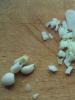
As an example - in the first photo I circled the mounting points of the future power supply with red rectangles - these are my variable resistances, banana sockets, a switch.
In the second photo, the second version of the power supply - everything is the same. In the third photo of the next version of the front panel - these are LED holders, enconder, sockets, switch.
2 - Then I draw the front panel in the FrontDesigner_3.0 program and print it out on a printer (I have a b/w printer at home), so to speak, a draft version.

3 - From plexiglass (also called acrylic glass or just acrylic), I cut out a blank for the future panel. I take plexiglass mainly from advertisers. Sometimes they give it away anyway, and sometimes they have to take it for money.


5 - Then, through these punctures, I make markings on acrylic (plexiglass) and on the body of my future design with a marker.


6 - I also make markings on the case for all other available holes on the panel, for indicators, switches, etc.

7 - But how to fix an indicator or display on the front panel, or the body of the structure?? If the body of the structure is made of plastic, then this is not a problem - I drilled a hole, countersunk it, put countersunk screws, support washers under the display (or tubes) and that's it, the problem is solved. And if the metal, and even thin? It won’t work like that here, you can’t get a perfectly flat surface under the front panel in this way and the appearance will no longer be the same.
You can of course try to fit the screws with reverse side cases and on thermal glue or glue with "epoxy", as you like. But I don’t like it so much, it’s too Chinese, for my beloved I do it. So here I do things a little differently.
I take countersunk screws of suitable length (these are easier to solder). I tin the screw attachment points and the screws themselves with solder (and flux for soldering metals), and solder the screws. On the reverse side, it may not be very aesthetically pleasing, but it is cheap, reliable and practical.


8 - Then, when everything is ready and all the holes are drilled, cut and processed, the panel pattern is printed on a color printer at home (or at a neighbor's). You can print a drawing where photographs are printed, you first need to export the file to a graphic format and fit its dimensions to the intended panel.
Then I collect all this "sandwich" together. Sometimes, so that the nut from variable resistance is not visible, you have to cut off its stem a little (grind off the shaft). Then the cap sits deeper and the nuts from under the cap are practically invisible.


9 - Look at some of the front panels of my designs, some of which are also shown at the beginning of the article under the title. Maybe, of course, not "super-duper", but quite well, and it will not be a shame to show your friends.


P.S. You can make it a little easier and do without plexiglass. If color inscriptions are not provided, then you can print the drawing of the future panel on a black and white printer, on colored or white paper, or, if the drawing and inscriptions are in color, then print it on a color printer, then laminate the whole thing (in order not to paper quickly slammed) and stick it on a thin Double-sided tape. Then the whole thing is attached (glued) to the body of the device in place of the intended panel.
Example:
An old printed circuit board was used for the front panel. The photographs show what the initial version of the design was like, and what it became at the end.


Or here are a couple of designs where the front panel was made using the same technology


Well, that's basically all I wanted to tell you!
Of course, everyone chooses for himself the paths available to him in his work, and in no case do I force you to accept my technology as a basis. It's just that maybe someone will take it, or some of its moments into service and just say thank you to me, and I will be pleased that my work was useful to someone.
With respect to you! (
The part about circuitry is mercilessly cut out - this is what we ourselves know how to do.
Making an amplifier is not as difficult as it seems. All work can be done at home in the kitchen, with a minimum set of tools and materials. But still I can get impressive results. In this article, I will tell you how to do it. I also will not use machines and will do all the work by hand.
For the case, you will need an aluminum square 15X15 millimeters, it can be more, but not less, otherwise the case will not have sufficient rigidity. First you need to cut the blanks.
I recommend that you first draw the body on paper and calculate all the dimensions, so that later it would not be excruciatingly painful. When I make cases, I proceed from the fact that all standard Hi-Fi class devices have cases 430 or 460 millimeters long, while their height and depth are not limited. The size of 460 millimeters seems too big to me, so I took the size of 430 millimeters. I plan to finish the body with glass 4 mm thick. It follows from this that the frame must be smaller than the final size of the amplifier. If there is a 4 mm glass cover and a 1.5 mm thick aluminum bottom, then the height of the frame should be 5.5 mm less than the planned size. And if you make the sidewalls glass, then two thicknesses of glass must be subtracted from the total length.
Well, the blanks are cut, you can start processing. Let's start with the vertical racks of the frame. Here, too, we must not forget that two thicknesses of the shelf of the square used must be subtracted from their height. In my case, with a total amplifier thickness of 60 millimeters, the thickness glass lid 4 mm, the bottom 1.5 mm and the thickness of the square shelf turned out to be a rack height of 51.5 millimeters.
I processed all the racks in a package, this will allow them to get the same height.

When the racks are ready, we proceed to the processing of the horizontal frame elements. Each end of the square must be cut at an angle of 45 degrees for convenient joining. You can draw on the school square (I promised not to use a professional tool).

Pay attention to the next two photos, they show how to cut off the end of the square.


The bevel should go to the shelf, forming an acute angle. You can pre-saw off most of the metal with a hacksaw, and finally finish it with a file. Make sure that all similar parts are the same length. To assemble a case with dimensions 430X250X60, you will need four squares 422 mm long and four squares 250 mm long. An hour later, I had all the blanks made, and I proceed to assemble the frame.

I will assemble on M3 screws, I could have riveted, but rivets have now become in short supply, and traction ones are not suitable for this business - they will have a head sticking out. Screws must be purchased with a countersunk head and sharpen the drill at an angle of 90 degrees to drill recesses for the screw head.

Two squares are assembled on one vertical stand, as shown in the picture.

And this is the view from the back.

For greater accuracy, you can drill holding the parts in a vise.

It should look like an aquarium.

Now we need to make the bottom and back wall. I made them from aluminum sheet 1.5 mm thick. But you can use roofing iron or plexiglass - it will not be worse. Just have to recalculate the height of the racks. I used a jigsaw to cut the blanks, but you can cut them in any way possible.

When cutting, do not try to immediately get into size, it is better to make a millimeter more and finally fit the protruding edge in place. Here, the bottom is ready. It must be screwed to the frame with screws with a pitch of no more than one hundred millimeters, this will eliminate its deflection.

Now you can cut the protruding part of the bottom to size.

The back of the case is done in the same way. It will be equipped with a power connector, input and output jacks. They must be purchased in advance.

We mark and drill holes in the back wall.

Well, everything is simple here - the holes are round, but you have to tinker with the power connector.

We mark the place for the future window and use a thin drill to drill holes as close to each other as possible. Then we bite the jumpers with side cutters ...


Five minutes of work with a file and the window is ready!

Now think about the legs of our future amplifier. They can be used ready-made from an old computer case, but I found suitcase legs that are made of soft plastic. They fit perfectly.

You can start making the front panel. I made it from an aluminum strip 5 mm thick, but this is not critical, it can be thinner, just a thick panel looks somehow prettier.

In the picture you can see some markings, this is what I forgot to mention. Specifically in this amplifier, I wanted to make an arrow level indicator. There must be some kind of highlight. But you can do without indicators, whoever does not make them can safely skip the entire description about indicators.
Indicators ... For them, I purchased two voltmeters.

And took them apart...

Of these, we need only the mechanism itself. Here it must be handled with the utmost care.

To give the indicator a professional look, we will combine them in one case and make a backlight. We transfer the markings from the original nameplate to the aluminum plate and cut it out with a needle file.


And you also need to make a bar that will cover the mechanism from prying eyes.

It should look something like what you see in the photo.

It is worth paying attention to the side covers - they are needed to complete the design. And three more holes in the center - there will be LEDs indicating the input is on. This is what it looks like from the back.

The whole structure rests on the square, which is located in the middle. Illumination will be carried out by a strip of blue LEDs. They are located in the upper part of the case, above the indicator.

Three red LEDs must be glued into the holes located in the center of the indicator.


Well, solder the board with resistors to the conclusions. The LEDs themselves are connected in parallel with the relay windings on the switching board.

Under the indicator, you need to cut a window, we will use the same technology as cutting a window under the power connector. Only here it is necessary to show maximum accuracy and patience - the appearance of the amplifier will depend on this.

Here I could not resist and milled a recess under the glass on the reverse side, but this is not mandatory. You can use a thin transparent film for laser printers, this film is very thin and will not affect the dimensions, which cannot be said about glass.

The holes for the buttons are drilled with a 8.4 mm drill bit. That's because I have an 8mm diameter aluminum bar that will make great buttons.

The chamfer in the hole is best done with a countersink, it is difficult to achieve with a drill flat surface.

The button itself is sawn off from a bar of the desired length and polished by hand using hand drill. On the reverse side, you need to drill a hole of 4 millimeters. The butt is desirable to polish.

The power switch is mounted on two long screws, this will allow you to accurately set its height so that the button does not rub in the hole.

The volume knob can be used ready, it will not worsen appearance. There are some beautiful pens for sale.


But I don't like it, I used a homemade one. Whoever has a familiar turner - I advise you to turn to him for help and make just such a pen.

And for completeness, you need to make a decorative ring.

In combination with a handle, this will take a completely finished look.

But once again I will say - this is not necessary, it will look great with a different handle. Remained work on finishing the body. The front panel must be carefully sanded. To do this, we will assemble a small device.

The panel is fixed on a chipboard base, a square is screwed on the side - it serves as a guide. Strip sandpaper with medium grain is attached to a segment of the same chipboard. Sandpaper moves along the panel and at the same time is pressed against the guide. This will allow you to get parallel risks on the panel.

During processing, the panel should be plentifully watered with kerosene. It can be poured into a spray bottle, it will be very convenient. The panel must always be damp. Do not rub dry! Hard-to-remove defects may remain.

In an hour you will be able to admire the results.

The volume knob can be polished with a drill.


The only thing left is to cut out the glass for finishing the case. I used a mirror for this gray color. The simplest thing is to order all this in a mirror workshop, but you can do it yourself. Cutting off glass is not a problem, but processing the edges is a must. Processing is done with sandpaper and water. Gradually reducing the numbers, you can achieve almost perfect polishing. But you can stop on a flat matte surface.

The side strips of glass are glued to the body with aquarium silicone.


Glass in the recess is glued with epoxy glue. After curing, excess adhesive is removed with a sharp blade.

We collect the indicator. The picture for the nameplate is drawn in any graphic editor and printed on white self-adhesive film.

It would also be nice to order decorative linings for the screws from the turner, they will give a professional look to the amplifier.

The case itself is covered with black spray paint, but this is also not a necessity - the frame is almost invisible. If the case cover is made of glass, by the way, good results gives ordinary mirror, you need to drill holes in it. I made them with a tubular drill. First, up to half the thickness on the back of the mirror ...

And then from the front. If you do it the other way around, you won't be able to see where to drill, and I don't advise you to drill through - in this case, chips are inevitable.

Now we take a red LED and a diameter of three millimeters. In the volume knob, a hole is drilled on the front side with a diameter of three millimeters, and on the back, almost to the end, it is necessary to drill it with a drill of four millimeters. A resistor is soldered to the LED, and the wires are insulated with tubes. It is advisable to use MGTF brand wire.

The resulting design is inserted into the hole and fixed with a drop of glue.

The handle is put in place, and the wires are passed into the gap between the panel and the axis. The wires from the LED are connected to the supply voltage.

Now that's it! It remains to fix the top cover. It is also desirable to put decorative linings under the screws. But you can use black screws.

The final step is to make the inscriptions on the front panel. The easiest option is to print them on a transparent self-adhesive film. That's exactly what I did.

Here is what you should end up with.


Without boasting, I will say that it took me sixteen hours to complete this work. So this amplifier is quite possible to build over the weekend. Success!
In this article I want to talk about how you can make good enough and high-quality cases for various, both small and large electronics. In general, the prices for factory cases prompted me to manufacture the case. Aluminum and metal cases are obscenely expensive, especially if they are medium and large sizes, and even plastic and those are not cheap. But I found a way out, so to speak, made an analogue of such cases as in the photo below, and then received excellent result I will continue to make such cases and further.
For the basis of my body, I took a segment profile pipe size 100 * 50 mm, with a wall thickness of 3 mm. I just needed a case of such dimensions so that it effectively dissipates heat due to mass and area. But now you can buy a profile pipe of any size, for example, for small electronics there are pipes 40 * 20 mm with a wall thickness of 2 mm, well, other sizes are also available everywhere, and most importantly, it's all pretty cheap. And for the manufacture you don’t need anything special, it’s enough to have a drill or a screwdriver to drill holes, well, cut it as needed with the help of a grinder. Below in the photo is what I got,
 >
>
The case consists of five main parts, dimensions 180*100*50 mm. The case itself is a piece of a profile pipe of the required length, I cut off 18 cm. I cut two side covers from the same profile pipe. They are pulled together by four studs that go through the entire case, they go through the corners and do not interfere with placing electronic parts inside. So that the controller does not press its back against the wall during installation and there is a gap for good cooling, I cut a 20 * 20 mm profile to get two L-shaped strips, which I screwed from the sides. Below in the photo are the body parts, cut out with an ordinary small grinder.
 >
>
 >
>
 >
>
Side covers are attracted to studs
 >
>
 >
>
 >
>
 >
>
After manufacturing, the body was painted with spray paint, before painting I walked with sandpaper, but I didn’t prime or degrease it, although it’s very desirable to do this so that the paint doesn’t lag behind and doesn’t peel off.
 >
>
 >
>
 >
>
 >
>
 >
>
Below is the video from which the photos are posted above.
In general, in this way you can make any cases for various electronics. The metal case has good heat dissipation, is durable, but really heavy and more suitable for stationary use.
The circuit is assembled, configured ... How much effort was spent on the circuit, searching for parts, assembling, configuring, and not much is left - the case!
It's no secret that a good body plays very well. big role and gives the structure a finished look. It often takes a long time before hands reach the manufacture of the case. What is it most commonly made from?
- plywood (wood)
- fiberglass (getinaks)
- duralumin
- plastic
- mailbox :)
- buy ready
I have a problem with the tree, well, I can’t work with it cleanly, I need good tool and enough space in the apartment. Fiberglass - I did it, I didn’t really like it. Dural must be found, and it's a little expensive these days. I personally am not ready to buy ready-made. Either the sizes are not suitable, then the price confuses.
In general, it remains either to make it from plastic or from a parcel box and suffer that none of your friends will appreciate the work of installing the board ... ..
So.
I chose plastic. Where to get it? 
In repair companies (firms, offices), with familiar system administrators. Everything will do: old keyboards, stubs from CD-ROMs, FDD, parts from printers, copiers (they are usually given away with gratitude in workshops - it's rubbish) and just plastic from something else. Plexiglas can be used. The main thing is that it dissolves in dichloroethane. 
Tool
There is not much of it: a metal ruler, a square, a cutter (made from a piece of cloth), a hacksaw for metal, files with a large notch, sandpaper (I take it in a hardware store, type P600 (fine grain) and P100 (larger) from Kona flex ) and dichloroethane plastic adhesive. Also, it is necessary to dissolve finely chopped pieces of plastic in dichloroethane, the consistency should be like that of a thick syrup. We will glue and fill small cracks with this solution.ATTENTION! Dichloroethane is toxic and volatile.
Begin
I saw plastic with a hacksaw with a sharp blade, not very fast, so that the plastic does not heat up. Nothing terrible will happen, it will just be difficult to cut if the plastic softens. I finish the edges with a file. If it is necessary to align the edge or adjust the size, then I do this with coarse sandpaper. I put a sheet of sandpaper on a flat surface, grain up, and without putting much effort I drive the edge of the workpiece along it. The main thing is to distribute the force evenly over the workpiece.glue
I need a flat surface, I have a piece of chipboard.I apply glue with a ton brush on both surfaces several times and press it tightly, if this is an angle, then I control it with a square. If it is necessary to glue two small pieces into one, then I grease the ends with glue, press the ends against each other on a flat surface. Attention! Be sure to reinforce the corners and joints with strips of plastic.


Treatment
After gluing, I proceed to the processing of the front surface. I fill large scratches, cracks on the front side with a mass of plastic dissolved in dichloroethane. After drying (approximately 10-12 hours), I process the surface with sandpaper until the surface is even.
Perhaps that's all - the body is ready for painting. 
This is what happened after the final finishing. 
All dimensions of the drawing are based on the dimensions of the parts, in this case on the dimensions of the speakers and the size printed circuit board, since I used a conventional charger as a power source, and not a battery, the dimensions of the case turned out to be much smaller. And remember - the case can be made from anything, for example, from plastic, wood, metal. Even from glass, the main thing is that everything is very neat and consistent. There is no need to hurry in the manufacture of the case, for example, it took me three days to implement the idea. Haste can only spoil valuable material.

So, let's start making our housing for the "ultrasonic mosquito repeller" - this article was published on our website earlier. First you need to choose a material. Without thinking twice, I decided to take plywood with a thickness of 4 mm, since it is not so difficult to find, and it can be easily processed, and in the end I have five years of experience working with wood. Now we determine the location of all the holes on the case - for a variable resistor, a switch, a power input and the shape of the holes for the speakers.

Let's sort it out in order: I took the most common variable resistor, but only picked up a plastic rotary knob to it and attached it with a nut, placing a washer. I took the switch from a burned-out computer power supply, it has antennae on the sides, so I didn’t fasten it with anything.

The input for the power wire was drilled with a diameter of 3.5 mm. And finally, I decided to make the holes for the speakers square (of course, you can also make them round), so that you can cut out square gaskets from rubber to hide bumps and move from plywood to mesh from the speakers. And yet, I almost forgot about the hole for the LED with a diameter of 4 mm and two ventilation holes on the sides of the case, on which they are also glued. Rubber bands - these are sold at the hardware store as spacers for water pipes, choose their diameter yourself. The back cover of the case is also made of plywood, and 3 mm thick rubber is glued on top. The lid is screwed with six self-tapping screws - my plywood sheet was slightly curved, but of course four can be used.

For the mesh, I made a small recess in the plywood - this can be seen in the drawing of the top panel.

After making all the details, I glued them with pva glue. Then he finally sanded and varnished from a can for car rims. Here is a drawing of this art:

The dimensions of the structure are not specified, since each has a different speaker.
Discuss the article TECHNOLOGY OF MANUFACTURING CASES