DIY magnetic levitation. Do-it-yourself magnetic levitation according to a simple scheme. We collect the coil. The frame can be made using a thin sheet of fiberglass and an old felt-tip pen
Levitron, as you know, is called a top rotating in the air above a box in which a magnetic field source operates. You can make a levitron from a popular hall sensor.
What is Levitron
ATTENTION! Found a completely simple way to reduce fuel consumption! Don't believe? An auto mechanic with 15 years of experience also did not believe until he tried it. And now he saves 35,000 rubles a year on gasoline!
Levitron is a toy. It makes no sense to buy if you know the manufacturing options homemade device. There will be nothing complicated in the design of such a Levitron if there is a conventional hall sensor, for example, bought for an automobile distributor, and left for future use.
You should know that the effect of levitation is always observed in sufficient narrow zone. Such realities somewhat limit the freedom of action of craftsmen, however, with the application of patience and time, you can always set up the Levitron efficiently and effectively. It will practically not fall or jump.
Levitron from the hall sensor
Levitron on the hall sensor and the idea of its manufacture is simple, like everything ingenious. Thanks to the strength of the magnetic field, a piece of any material with electromagnetic properties rises into the air.

To create the effect of "hanging", hovering in the air, the connection is made with a high frequency. In other words, the magnetic field, as it were, lifts and throws the material.
The scheme of the device is too simple, and even a schoolboy who has not spent physics lessons in vain will be able to build everything on his own.
- We need an LED (its color is selected depending on individual preferences).
- Transistors RFZ 44N (although any field worker close to these parameters will do).
- Diode 1N 4007.
- Resistors for 1 kOhm and 330 Ohm.
- Actually, the hall sensor itself (A3144 or another).
- Copper winding wire with a size of 0.3-0.4 mm (about 20 meters will be enough).
- Neodymium magnet in the form of a tablet 5x1 mm.
- 5 volt mobile phone charger.
Now in detail about how the assembly is carried out:
- A frame for an electromagnet is made with exactly the same parameters as in the photo. 6 mm - diameter, about 23 mm - winding length, 25 mm - cheek diameter with a margin. A frame is made from cardboard and a regular notebook sheet, using superglue.

- End copper wire is fixed on the coil, and then winding is carried out (approximately 550 turns). It does not matter in which direction to wind. The other end of the wire is also fixed, while the coil is set aside.
- We solder everything according to the scheme.

- The hall sensor is soldered to the wires, and then placed on the coil. It is necessary to put it inside the coil, fix it with improvised means.
Attention. The sensitive zone of the sensor (it can be determined from the documentation for the hall sensor) should look parallel to the ground. Therefore, before inserting the sensor into the coil, it is recommended to slightly bend this place.

- The coil is suspended, it is powered through the previously soldered board. The coil is fixed by means of a tripod.

Now you can check how Levitron works. Any electrified material can be brought to the coil from below. It will either be attracted by the coil or repelled, depending on the polarity. But we need the material to hang in the air, soar. So it will be, if the shape of the material is not too small in relation to the coil.
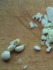
Note. If the pill magnet is small, it will not levitate very effectively. May fall. To eliminate flaws in the work, it is necessary to shift the center of gravity of the material to the bottom - an ordinary piece of paper is suitable as a load.
As for the LED, you can not put it. On the other hand, if you want more effect, you can organize a show with lights.
Homemade levitron in a classic version without a sensor
As you can see, thanks to the presence of a hall sensor, it was possible to make a quite spectacular toy. However, this does not mean at all that it cannot do without a sensor. Against, homemade levitron in the classic version, it is only a large magnet from the speaker (13-15 cm in diameter) and a small ring magnet for the top (2-3 cm in diameter), without using a sensor.
The axis of the top is usually made of old pen or a pencil. The main thing is that the rod is selected so that it fits snugly in the center of the ring magnet. The excess part of the handle is then cut off (about 10 cm in length, together with a fixed top magnet, that's what you need).
The classic Levitron manufacturing scheme also implies the presence of a dozen different washers cut from thick paper. What are they for? If in the case described above, paper was also used, and as we remember, to shift the center of gravity down or, more simply, to adjust. The same is true here. The washers will be needed for the ideal setting of the top (if necessary, they are planted after the ring magnet on the rod).

Attention. In order for a homemade spinning top to levitate perfectly, in addition to setting it up with washers, you need not to make a mistake with the polarity. In other words, align the ring magnet with the large magnet.

But that's not all. As in the first case (using a Hall sensor), and in the second, it is necessary to achieve the ideal evenness of the source of attraction. In other words, put a large magnet on the ideal flat surface. To achieve this, apply wooden coasters different thickness. If the magnet does not sit evenly, the stands are placed on one side or on several, thus evenness is adjusted.
Platform levitrons
The platform scheme of the Levitron differs, as a rule, in the presence of not one, but several source magnets. The material floating in the air or the top will in this case tend to fall on one of the magnets, having shifted from the vertical axis. To avoid this, you need to be able to correct the central zone of attraction, and do it perfectly accurately.
And here those same coils come to the rescue, with a hall sensor inserted inside. Let there be two such coils, and they should be placed exactly in the middle of the platform, between the magnets. On the diagram, it will look like this (1 and 2 are magnets).

From the diagram it becomes clear that the purpose of controlling the coils is to create a horizontal force, a center of attraction. This force is formally called Fss, and it is directed towards the equilibrium axis when a displacement occurs, indicated on the diagram as X.
If you connect the coils so that the pulse creates a zone with reverse polarity, then you can solve the issue with the offset. Any physicist will confirm this.
Any old DVD player is selected as a case for the construction of a platform levitron. All the “insides” are removed from it, magnets and coils are installed, and for the sake of beauty, the upper part is closed with a practical thin lid, you can transparent material(transmitting a magnetic field).
The hall sensors must protrude through the holes of the platform, must be soldered on the unbent legs of the connectors.
As for magnets, these can be round elements 4 mm thick. It is desirable that one of the magnets be more than a second by diameter. For example, 25 and 30 mm.
There are more complex options levitrons, made according to the scheme of spinning top, located inside a small globe. These levitrons can also be built using hall sensors - effective components that have revolutionized the automotive industry and other areas of human activity.
Levitron is a toy that demonstrates the levitation of a spinning top in which Neodymium magnet over a ferrite magnet of a larger diameter. It looks amazing!Materials for the manufacture of Levitron
So, we need three ring-shaped magnets with sufficient power to make a toy. Magnets from low-frequency speakers, whose service life has long expired, are quite suitable for our purpose.In order to make a top, you will need a neodymium magnet. You can take it from the speaker, which has the inscription "Neodium transducer". Similar speakers are used in cell phones. The strongest permanent magnet today is neodymium, made from an alloy of neodymium, boron, and iron. Heat will adversely affect it, so this magnet should be protected from heat. So the magnet cell phone can be of two types - in the form of a round plate or in the form of a ring. The ring magnet is put on the top itself strictly in the center, and the tablet-shaped magnet is glued to the axis of the top from below. The material for the top itself should be lightweight material such as composite or plastic.

Levitron setting
The setting should be approached with particular scrupulousness, because this part of the work is crucial and is the most time-consuming. Ring magnets must be connected to each other by opposite polarities. A plate (not made of metal) up to 1 cm thick should be installed on top of them. The top will be carefully installed in the base of the Levitron - the center of the magnet. If you notice that the top deviates to the side, then the magnet needs to be replaced with another one with a larger diameter.To start the top, you will need a few more elements with which you can adjust the thickness of the platform in order to achieve normal rotation of the top. We will need plexiglass plastic with paper sheets. If the spinning top is spinning normally, we begin to gently raise the platform until it flies up.
If our spinning top flies up with excessive swiftness, its weight should be increased. If it deviates in one direction, then you can correct the situation by placing paper sheets under the opposite one. These actions allow you to adjust the base of our toy so that it is clearly at sea level.
And a video with levitrons ...
A short video about what the made levitron is like:
www.youtube.com/watch?feature=player_embedded&v=vypjmqq9...
If someone is not afraid to do the same interesting thing, then here you are detailed instructions:
A bit of theory
Let's start, perhaps, with the mechanical scheme of the platform levitron, which has developed in my understanding. The magnet that hovers above the platform, I will here for brevity call the word "chip".
Levitron platform sketch(top) is shown in Fig. 1.

On fig. 2 - power diagram of a vertical section along the central axis of the platform (as I imagine it) at rest and without current in the coils. All is well, except that the state of rest in such a system is unstable. The chip tends to move away from the vertical axis of the system and slam onto one of the magnets with force. When “feeling” the space above the magnets with a chip, a force “hump” is felt above the center of the platform with the top lying on the central axis.

mg - chip weight,
F1 and F2 - the forces of interaction of the chip with the magnets of the platform,
Fmag - the total impact that balances the weight of the chip,
DH - Hall sensors.
On fig. 3. shows the interaction of the chip with the coils (again, in my opinion), and the rest of the forces are omitted.

Figure 3 shows that the purpose of coil control is to create a horizontal force Fss, always directed towards the equilibrium axis when a displacement occurs. X. To do this, it is enough to turn on the coils so that the same current in them creates a magnetic field in the opposite direction. There was nothing left: measure the offset of the chip from the axis (the value X) and determine the direction of this displacement using Hall sensors, and then pass currents in the coils of a suitable strength.
Simple repeat electronic circuits- not in our traditions, especially since:
- two TDA2030A are not available, but there is a TDA1552Q;
- there are no SS496 Hall sensors (available for about $2 each), but there are sensors similar to HW101, 3 pcs for free in each CD or DVD drive drive;
- too lazy to mess with bipolar power.
Datasheets:
SS496 - http://sccatalog.honeywell.com/pdbdownload/images/ss496.seri...HW101- http://www.alldatasheet.com/datasheet-pdf/pdf/143838/ETC1/HW101A.html
The circuit consists of two identical amplifying channels with differential inputs and bridged outputs. On fig. 4 shows the complete diagram of only one amplification channel. The chips used were LM358 (http://www.ti.com/lit/ds/symlink/lm158-n.pdf) and TDA1552Q (http://www.nxp.com/documents/data_sheet/TDA1552Q_CNV.pdf).

A pair of Hall sensors is connected to the input of each channel so as to supply a differential signal to the amplifier. The outputs of the sensors are switched on in opposite directions. This means that when a pair of sensors is in a magnetic field with the same intensity, zero differential voltage is supplied from it to the input of the amplifier.
Balancing resistors R10 are multi-turn, old, Soviet ones.
In an attempt to squeeze a sufficiently high gain out of the amplifier, I got a banal self-excitation, presumably due to a mess on the circuit board. Instead of “cleaning”, frequency-dependent RC chains R15C2 are introduced into the circuit; they are not required. If you still had to install them, then the resistance R15 must be selected as the largest, at which self-excitation goes out.
The power supply of the entire device is an adapter (pulse) for 12V 1.2A, reconfigured to 15V. Power consumption in normal condition(with the fan turned off) in the end turned out to be quite modest: 210-220 mA.
Design
A 3.5” floppy drive shroud was chosen as the case, which approximately corresponds to the dimensions of the prototypes. To level the platform
legs are made of M3 screws.
A figured hole is cut out in the upper part of the body, clearly visible in Fig. 5. Subsequently, it is closed with a decorative mirror plate made of chrome-plated brass, fixed with screws from hard drives.

1 - installation locations for magnets (bottom) and balance indicators (optional)
2 - "pole pieces" of coils
3 - Hall sensors
4 - backlight LEDs (optional)
The Hall sensors are located in the holes of the fiberglass base of the platform and are soldered on the unbent legs of the connectors (I don’t know the type). The connectors looked like in Fig.6.

The sensors are soldered from the motors of the CD or DVD drive. There they are located under the edge of the rotor and are clearly visible in Fig. 7. For one channel, you need to take a pair of sensors from one engine - so they will be the most identical. Soldered sensors - in Fig.8.


For coils, plastic spools were purchased for sewing machines, but there was little room for winding on them. Then cheeks were cut off from the spools and glued to pieces of thin-walled brass tube outer diameter 6mm and length 14mm. The tube used to be a segment of a telescopic rod antenna. On four such frames with a 0.3 mm wire, the windings are wound “almost in layers” (without fanaticism!) Until they are filled. The resistance is aligned to 13 ohms.
Magnets - rectangular 20x10x5 mm and disk magnets with a diameter of 25 and 30 mm 4 mm thick (Fig. 9) - I still had to buy ... Rectangular magnets are installed under the base of the platform, and chips are made from disk magnets.

View of the device from below and behind (upside down) - in fig. 10 and 11 (one legend for both figures). The mess, of course, is picturesque ...
The U2 TDA1552Q chip (3) is located on the heat sink (9), which used to work on the video card. The radiator itself is fixed with screws on the bent parts of the top case cover. A power socket (1), control sockets (2) and a thermal control unit (5) are also fixed to the radiator (9).
A piece of fiberglass, which used to be a keyboard, serves as the base of the platform. Coils (7) are fixed on the base with M4 screws and nuts. Magnets (6) are fixed on it with the help of clamps and self-tapping screws.
The control jacks (2) are made from a computer power connector and are fixed on the back of the device near the balancing resistors (10) so that they are easily accessible without disassembly. The jacks are connected, of course, to the outputs of both channels of the amplifier.
The circuitry of the preamplifier and its power regulator, including balancing resistors (10), is mounted on breadboard and as a result of the adjustment turned into a picturesque pigsty, macro photography of which had to be refrained from.


1 - fastening the power socket
2 - control sockets
3 - TDA1552Q
4 - power switch
5 - thermal control unit
6 - magnets under the clamps
7 - coils
8 - magnetic shunts
9 - heat sink
10 - balancing resistors
Adjustment
Setting zeros at the outputs of both channels at each debugging start is mandatory. It is possible without fanaticism: + -20 mV is quite acceptable accuracy. There may be some interference between the channels, so with a significant initial deviation (more than 1-1.5 volts at the channel output), it is better to set zeros twice. It is worth remembering that with an iron case, the balance of a disassembled and assembled device is two big differences.
Checking channel phasing
The chip must be taken in hand and placed above the center of the platform of the included Levitron at a height of approximately 10-12mm. Channels are checked one by one and separately. When the chip is shifted by hand along the line connecting the sensors opposite from the center, the hand should feel a noticeable resistance created by magnetic field coils. If no resistance is felt, and the hand with the chip "blows" away from the axis, you need to swap the wires from the output of the channel under test.
Adjusting the position of the floating chip
On videos about homemade platform levitrons, you can often see that the chip is hovering in an inclined position, even if it is made on the basis of disk magnets, that is, it is quite well symmetrical. Not without distortion in the described design. Perhaps the metal case is to blame ...
First thought: move the magnets down from the side where the chip is unnecessarily “supported”.
The second thought: move the magnets further from the center from the side where the chip is unnecessarily “supported”.
The third thought: if the magnets are displaced, then the magnetic axis of the system of permanent magnets of the platform will be skewed relative to the magnetic axis of the coil system, due to which the behavior of the chip will become unpredictable (especially with different weights).
The fourth thought - to make the magnets stronger on the side where the chip is tilted - was discarded as unrealizable, because there was nowhere to get a wide range of magnets to fit.
The fifth idea: to make the magnets weaker on the side where the chip is unnecessarily “supported” – turned out to be successful. Moreover, it is quite simple to implement. A magnet, as a source of a magnetic field, can be shunted, that is, short-circuited part magnetic flux, so that in the surrounding space the magnetic field will become slightly weaker. As magnetic shunts, small ferrite rings (10x6x3, 8x4x2, etc.) were used, plucked free of charge from dead economy lamps (8 in Fig. 10). These rings just need to be magnetized to a too strong magnet (or two or three) on the side that is farther from the center of the platform. It turned out that by choosing the number and size of shunts for each "too strong" magnet, it is possible to quite accurately level the position of a floating symmetrical chip. Don't forget to perform electrical balancing after every change in the magnetic system!
Options
Options include: amplifier unbalance indicators, thermal control unit, lighting, and adjustable platform feet.
The amplifier unbalance indicators are two pairs of LEDs located at the same radii as the sensors, in the thickness of the fiberglass base of the platform (1 in Fig. 5). LEDs, very small and flat, used to work in some kind of modem, but they will also work from an old mobile phone (in SMD version). The LEDs are recessed in the holes, since the chip, breaking off from the center, flops onto the nearest magnet and is quite capable of destroying the LED.
The indicator scheme for one channel is shown in fig. 12. LEDs must be with an operating voltage of 1.1-1.2 V, i.e. simple red, orange, yellow. At higher LED voltages (2.9-3.3 V for super-bright ones), the number of diodes in the D3-D6 chain should be recalculated to minimize the "dead zone" - the minimum voltage at the channel output, at which none of the LEDs glows.

I arranged the indicators so that the one towards which the chip is shifted from the center shone. Indicators help to easily hang a chip over the Levitron, as well as to level the platform. In the normal state, they are all redeemed.
The diagram of the thermal control unit is in fig. 13. Its purpose is to prevent the final amplifier from overheating. At the output of the thermal unit, a fan 50x50 mm 12V 0.13A from the computer is turned on.

In the thermal node circuit, it is easy to recognize a slightly modified Schmitt trigger. Instead of the first transistor, a TL431 chip was used. The type of transistor Q1 is indicated conditionally - I stuck the first NPN that came across that could withstand the operating current of the fan. As a temperature sensor, a thermistor found on an old motherboard on the processor socket. The temperature sensor is glued to the heatsink of the final amplifier. By selecting the resistor R1, you can adjust the thermal unit for operation at a temperature of 50-60C. Resistor R5, together with the collector current Q1, determines the amount of hysteresis in the circuit relative to the voltage at the control input U1.
In the diagram in fig. 13 resistor R7 is introduced to reduce the voltage on the fan and, accordingly, the noise from it.
On fig. 14 shows how the fan is embedded in the bottom cover of the case.

Another way to use a thermal node is to connect a final amplifier chip to the MUTE control pin (Fig. 15). The value of the R5 rating indicated on the diagram assumes that MUTE (pin 11 of the U2 chip in Fig. 4) is connected to the power supply through a 1kΩ resistor (NOT directly, as in the datasheet!). In this case, a fan is not needed. True, when the MUTE signal is applied to the amplifier, the chip falls, and after the MUTE signal is removed, it itself (for some reason?) does not take off.

Illumination - 4 bright LEDs with a diameter of 3 mm, located obliquely to the center in the holes of the platform base and decorative plate in those places where the chip does not fall. They are connected in series and through a 150 Ohm resistor to the 15V device's general power supply circuit.
Conclusion
load capacity
In order to “finish off” the topic, the “cargo characteristics” of the Levitron with chips of 25 and 30 mm in diameter were removed. I here called the cargo characteristics the dependence of the height of the hovering of the chip above the platform (from the decorative plate) on the total weight of the chip.
For a chip with a 25 mm magnet and a total weight of 19 g, the maximum height was 16 mm, and the minimum was 8 mm with a weight of 38 g. Between these points, the characteristic is almost linear. For a chip with a 30 mm magnet, the load characteristic turned out to be between the points of 16 mm at 24g and 8 mm at 48g.
From a height below 8 mm from the platform, the chip falls, being attracted to the iron cores of the coils.
DO NOT do like me!
First, do not save on sensors. "Naked" Hall sensors, taken out in pairs for each channel of two engines (that is, almost the same!) - still show their ugly large temperature coefficient of resistance. Even with the same power circuits and back-to-back switching of the sensor outputs, you can get a noticeable zero shift at the channel output when the temperature changes. Integrated sensors SS496 (SS495) have not only a built-in amplifier, but also thermal stabilization. The internal amplifier of the sensors will make it possible to significantly increase the overall gain of the channels, and the circuit for their power supply is simpler.
Secondly, one should, if possible, refrain from placing the Levitron in an iron case.
Thirdly, bipolar power is still preferable, because gain control and zero adjustment are easier.
Thank you for your attention!
How it works: In this circuit, an attractive force is generated between the electromagnet and permanent magnet. The equilibrium position is unstable, and therefore the system is used automatic control and management. The control sensor is a magnetically controlled position sensor based on the Hall effect MD1. It is located in the center of the end of the coil and is fixed. The coil is wound with varnished wire 0.35-04 mm, and has about 550 turns. LED HL1 shows with its glow that the circuit is working. Diode D1 ensures the speed of the coil.
The scheme works as follows. When turned on, current flows through the coil, which creates a magnetic field and attracts the magnet. In order for the magnet not to turn over, it is stabilized by attaching something to it from below. The magnet takes off and is attracted to the electromagnet, but when the magnet enters the range of the position sensor (MD1), it turns it off with its magnetic field. The sensor, in turn, sends a signal to the transistor, which turns off the electromagnet. The magnet falls. Leaving the sensor sensitivity zone, the electromagnet turns on again and the magnet is again attracted to the electromagnet. Thus, the system continuously oscillates around a certain point.
Scheme:
For assembly we need:
1) resistors 270Ω and 1kΩ (0.125W)
2) transistor IRF 740
3) LED
4) diode 1N4007
5) Hall sensor AH443
6) breadboard
7) varnished wire 0.35-0.4mm
+ housing, soldering iron, etc.
Scheme:
We collect the coil. The frame can be made using a thin sheet of fiberglass and an old felt-tip pen.
Cut out: (approximate coil size: height - 22mm, diameter - 27mm)
Gluing together:
We wind about 550 turns: (varnished wire 0.35-0.4mm, in bulk, but more or less we try to wind evenly)
Soldering the control board: (I used a regular 3.5 mm miniJack as a power connector)
Pinout:
For ease of assembly, you can use pin connectors:
We cut out all the necessary holes in the case:
Putting everything in place:
Now you need to make a mount for the coil:
We fasten to the body and fasten the coil:
This is how you need to bend the Hall sensor, solder the wires to it:
We connect everything to the heap:
After we get the magnet, you need to determine which side to orient it to the electromagnet. To do this, we place and temporarily fix the Hall sensor at the very bottom of the coil. We turn on the Levitron (the LED should light up) and bring the magnet. If it is attracted to the coil, then the magnet is oriented correctly, but if the magnetic field of the coil pushes it out, then the magnet must be turned over. Attach something light to the bottom of the magnet. In my case, it's an LED.
By moving the Hall sensor, we achieve stable hovering at the maximum distance from the coil. We fix it:
Magnetic levitation always looks impressive and bewitching. Such a device today can not only be bought, but also made by yourself. And in order to create such a magnetic levitation device, it is not necessary to spend a lot of money and time on it.
IN this material a diagram and instructions for assembling a magnetic levitator from inexpensive components will be presented. The assembly itself will take no more than two hours.
The idea of this device called Levitron is very simple. The electromagnetic force lifts a piece of magnetic material into the air, and in order to create a floating effect, the object rises and falls in a very small range of heights, but at a very high frequency.
To assemble a Levitron, you only need seven components, including a coil. The scheme of the magnetic levitation device is presented below.

So, as we see from the diagram, in addition to the coil, we need a field effect transistor, for example, an IRFZ44N or another similar MOSFET, a HER207 diode or something like 1n4007, 1KΩ and 330Ω resistors, an A3144 Hall sensor, and an optional indicator LED. The coil can be made independently, this will require 20 meters of wire with a diameter of 0.3-0.4 mm. To power the circuit, you can take a 5 V charger.

To make a coil, you need to take the base with the dimensions shown in the following figure. For our coil, it will be enough to wind 550 turns. Having finished winding, it is desirable to insulate the coil with some kind of electrical tape.


Now solder almost all the components except the Hall sensor and the coil on a small board. Place the Hall sensor in the hole of the coil.


Fix the coil so that it is above the surface at some distance. After that on this device magnetic levitation can be powered. Take a small piece of neodymium magnet and bring it to the bottom of the coil. If everything is done correctly, then the electromagnetic force will pick it up and keep it in the air.

If this device does not work properly for you, then check the sensor. Its sensitive part, that is, the flat side with the inscriptions, should be parallel to the ground. Also, for levitation, the shape of the tablet, which is inherent in most sold neodymium magnets, is not the most successful. So that the center of gravity does not “walk”, you need to transfer it to the bottom of the magnet, attaching something not too heavy, but not too light either. For example, you can add a piece of cardboard or thick paper, as in the first image.