The volume of water in the pipes of the underfloor heating. How to calculate a water heated floor - the task of successive approximation
That's when these tricky mathematical terms suddenly catch you on life path- when you try to somehow discipline your process of laying a water-heated floor. Do not think that the resulting calculations will be one to one then implemented in practice.
In no case. You will have to check and recheck the received figures more than once, correct the initial data, gradually approaching those values that will most accurately reflect the properties of your floor heating system.
When the calculation is corrected by practice

The first thing to determine is the pipe layout.
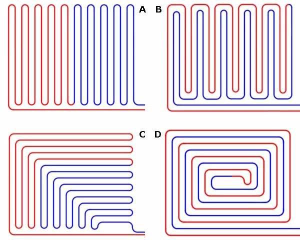
Possible pipe schemes
In laying practice, add four schemes that are used everywhere:
- A - snake;
- B - double snake;
- C - corner snake;
- D - snail.
Already based on the selected scheme, it is possible to calculate the volume of water as a whole in the system.
Main indicator
Calculation of the volume of water in the system requires a preliminary determination of the parameters of the selected scheme.
Among them:
- the selected type itself - select "A";
- distance from the pipeline to the wall - from the recommended range of 20-30 cm, we select the minimum distance of 20 cm;
- the distance between the rows of pipes - between the recommended from 10 to 50 cm, we choose exactly in the middle - 30 cm (let's not forget, we have a pipe with a diameter of about 30 mm, so the actual distance between the pipes will be 27 cm);
- inner diameter of the pipe - choose a pipe with an inner diameter of 20 mm;
In addition, we have at our disposal data on the working heated area:
- width - 4 m;
- length - 5 m.
Laying will be carried out parallel to the smaller side.
Based on the given data, we get:
- the number of pipe lines “back and forth” is 15, while there remains another 10 cm in the remainder, which we “throw” to increase the distance from the wall of a shorter length - 5 cm on both sides;
- given that from the side of the collector the distance to the pipe will be 40 cm (and not 20, 20 is still allocated to the outlet channel), the total length of the pipe in the circuit will be:
15 x 3.40 = 51 meters,
Helpful advice!
A length of 100 meters is the maximum recommended, but we advise you to constantly strive to reduce it, up to the creation of two contours.
So, if you choose between one circuit of 160 meters and two of 80 meters, it is better to choose two.
The length of the contours does not have to be the same, but do not allow a difference in their lengths of more than 15 meters.
- now we get the total length of the pipe from the inlet to the collector outlet, it will be 5 meters more - 56;
- thus, it becomes possible to calculate the volume of water required for an underfloor heating system using the cylinder volume formula:
V = pi x R x R x D,
where R is the radius of the pipe in cm, in our case it is exactly 1;
D - pipe length - 5600 cm.
Calculations give V = 3.14 x 1 x 1 x 5600 = 17584 cc.
In other words, more than 17 and a half liters of water will be required to completely fill the system.
Helpful advice!
Please note that this need of 17.5 liters will place an additional burden on the operation of the pump of the entire heating system at home.
Therefore, it is very important to carry out, and throughout heating system from the boiler to the sensors.
Otherwise, the pump simply will not cope with the additional load.
Additional calculations
In addition to the above three most important characteristics:
- pipe scheme;
- their length;
- and the internal volume, or the required volume of the coolant -
several other equally important ones are calculated.
Heat carrier temperature
There are two ways to answer the question about the temperature of the coolant:
- firstly, the temperature in any water heating system is never higher than 60 degrees;
- and, secondly, floor coverings impose their own limitation on temperature - the vast majority of them impose restrictions of a maximum of 35 degrees;
In any case, to control the coolant in the system, you must use. For real control over the functioning of the system, we recommend installing two sensors - after the pump, at the inlet to the system, and before the pump, at the outlet.
It is considered that the system is functioning properly if the temperature difference does not exceed 5 degrees. Otherwise, the heat losses are too great and it is required to establish the cause of these losses.
As a derivative of the coolant temperature - the temperature on the floor surface.
- for residential premises - 29 degrees;
- for the checkpoint - 35;
- for official - 33.
Collector Data
The entire piping system of the floor eventually closes on the manifold. It is very important to choose this device correctly and install it correctly according to the inputs and outputs of all circuits.
Here are the tasks to be solved:
- The first, which significantly increases such an indicator as the price of a warm water floor per m2 - what should the manifold cabinet be, what are its dimensions?
- Here it is impossible to give an unambiguous answer, a lot depends on the power of the system, the number of circuits, in the end, on the location of the cabinet. For orientation, we advise you to refer to the products of Valtec.
The internal collector cabinets of this company are designated by the letters ШРВ and have the following dimensions (length x depth x height, mm):- ShRV1 - 670 x 125 x 494;
- ShRV2 - 670 x 125 x 594;
- ShRV3 - 670x125 x 744.
Outdoor models - SRN:
- SHRN1 - 651 x 120 x 453;
- SHRN2 - 651 x 120 x 553;
- SHRN3 - 651 x 120 x 703.
All 6 presented models are designed to connect two circuits of the floor heating system, which is quite suitable for a room of 40 square meters, or 5 by 8 meters.
- Due to the need to supply and connect pipes, and most importantly - to support the system in the future, is it another task to obtain a convenient mounting height for the manifold cabinet?
- This question is largely about usability, which means that anyone can set any height that is comfortable, however, three factors must be kept in mind:
- the cabinet is installed before pouring concrete screed floor and flooring placement, therefore, their height must also be taken into account in order to provide convenient access to the internal connectors of the collector;
- maintenance of the cabinet will have to be dealt with constantly, so the convenience of working with it when choosing a height will come first;
- at the same time, the collector cabinet is not a piece of furniture and you always want to hide it a little; hence the conclusion is optimal height installation of the cabinet relative to the finish coating - 20-25 cm.
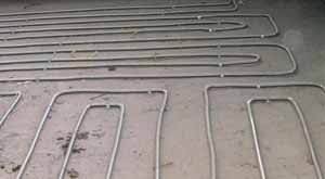
The inconvenience of working with metal pipes the fact is that they are difficult to bend sufficiently to provide the required flow of water - in any case, right angles should be avoided
No need to count yourself
The choice of a water floor heating system is influenced by external factors, up to the characteristics of the floor finish. Therefore, in order not to forget anything, or maybe to coordinate your calculations with the calculations of existing methods, we recommend using a water-heated floor calculator, of which you can find a lot on the network.
Be prepared that the underfloor heating calculator will ask for the following parameters:
- room length and
- its width - these two parameters are always at hand;
- desired comfortable temperature the air in the room that the system will create and maintain;
- temperature at the inlet to the pipelines of the system, up to the collector - we recommend taking this indicator from the floor covering recommended by the manufacturers, which you intend to place above the system;
- temperature at the outlet, after the collector - lay immediately 5 degrees less than the inlet temperature;
- design capacity of the premises - here you can not do without consulting with specialists;
- pipe laying step, or distance between them;
- floor finish type best options calculators can offer in the drop-down list the choice of any up to laminate and porcelain stoneware;
- the length of the supply line - usually meaning from the collector to the first turn of the circuit;
- thickness of the waterproofing layer - this parameter matters only if the waterproofing is located above the system;
- thickness of the starting screed - some take this value into account, although the starting screed is always under the system;
- the thickness of the finishing screed is the one in which the system itself is concreted.
conclusions
The calculation of a water-heated floor is always approximate, but this does not mean that it should not be carried out, and even more so, the data obtained should not be taken into account. After all, they accurately reflect both the configuration of the room, the layout of the pipes, and the characteristics of this installation.
And these are already parameters that are recommended to be observed as accurately as possible. Calculations will allow you to “feel” your idea with floor heating and, perhaps, understand the feasibility of its use. There will be time to think things over carefully, and this is another positive factor in the calculation.
The video in this article will help you not to miss the most important design characteristics of a warm water floor in the whole “swarm” that you need to pay attention to first.
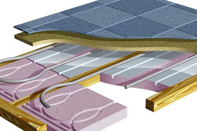
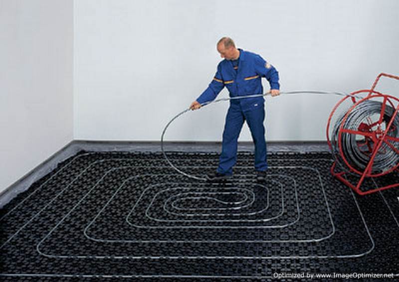
The most common way to implement systems floor heating are monolithic concrete floors made by the so-called “wet” method. The floor structure is a “layer cake” of various materials (Fig. 1).
Fig.1 Laying underfloor heating loops with a single coil
Installation of the underfloor heating system begins with the preparation of the surface for the installation of a warm floor. The surface must be leveled, the surface irregularities must not exceed ±5 mm. Irregularities and protrusions of no more than 10 mm are allowed. If necessary, the surface is leveled with an additional screed. Violation of this requirement can lead to “airing” of pipes. If in the room below high humidity it is desirable to lay waterproofing (polyethylene film).
After leveling the surface, it is necessary to lay a damper tape at least 5 mm wide along the side walls to compensate for the thermal expansion of the underfloor heating monolith. It should be laid along all walls framing the room, racks, door frames, bends, etc. The tape must protrude at least 20 mm above the planned height of the floor structure.
After that, a layer of thermal insulation is laid to prevent heat leakage into the lower rooms. As thermal insulation, it is recommended to use foamed materials (polystyrene, polyethylene, etc.) with a density of at least 25 kg/m 3 . If it is impossible to lay thick layers of thermal insulation, then foil thermal insulation materials 5 or 10 mm thick. It is important that foil thermal insulation materials have protective film on aluminium. Otherwise, the alkaline environment of the concrete screed destroys the foil layer within 3-5 weeks.
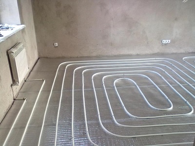
The layout of pipes is carried out with a certain step and in desired configuration. In this case, it is recommended that the supply pipeline should be laid closer to the outer walls.
When laying “single coil” (Fig. 2), the temperature distribution of the floor surface is not uniform.
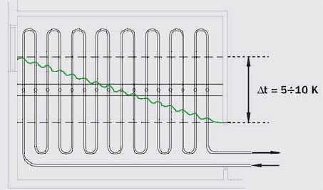
Fig. 2 Laying the underfloor heating loops with a single coil
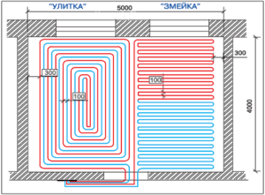
In spiral laying (Fig. 3), pipes with opposite flow directions alternate, with the hottest section of the pipe adjacent to the coldest. This results in an even temperature distribution over the floor surface.
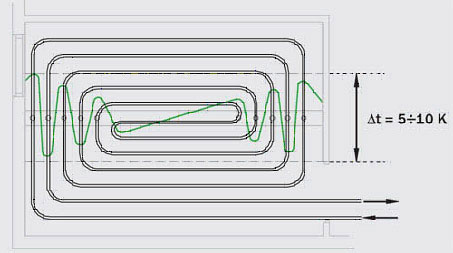
Fig. 3 Laying the loops of the warm floor in a spiral.
The pipe is laid according to the markings applied to the heat insulator, with anchor brackets every 0.3 - 0.5 m, or between special ledges of the heat insulator. The laying step is calculated and lies in the range from 10 to 30 cm, but should not exceed 30 cm, otherwise there will be uneven heating floor surface with the appearance of warm and cold stripes. The areas near the outer walls of the building are called boundary zones. Here it is recommended to reduce the pipe laying step in order to compensate for heat loss through the walls. The length of one contour (loop) of a warm floor should not exceed 100–120 m, the pressure loss per loop (together with fittings) should not exceed 20 kPa; the minimum speed of water movement is 0.2 m / s (to avoid the formation of air pockets in the system).
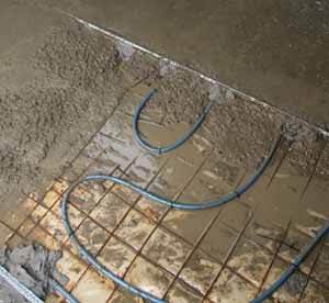
After laying out the loops, immediately before pouring the screed, the system is pressure tested at a pressure of 1.5 from the working one, but not less than 0.3 MPa.
When pouring a cement-sand screed, the pipe must be under a water pressure of 0.3 MPa at room temperature. The minimum pouring height above the pipe surface must be at least 3 cm (the maximum recommended height, according to European standards, is 7 cm). Cement-sand mixture must be at least brand 400 with a plasticizer. After pouring, it is recommended to “vibrate” the screed. With a length monolithic slab more than 8 m or an area of more than 40 m 2, it is necessary to provide seams between the plates with a minimum thickness of 5 mm, to compensate for the thermal expansion of the monolith. When pipes pass through the seams, they must have a protective sheath with a length of at least 1 m.
The system is started only after the concrete has completely dried (approximately 4 days per 1 cm of screed thickness). The water temperature when starting the system should be at room temperature. After starting the system, daily increase the temperature of the supply water by 5°C to operating temperature.
Basic temperature requirements for underfloor heating systems
- It is recommended to take the average temperature of the floor surface no higher (according to SNiP 41-01-2003, clause 6.5.12):
- 26°C for rooms with permanent residence of people
- 31°C for rooms with temporary stay of people and bypass paths of swimming pools
- The temperature of the floor surface along the axis of the heating element in children's institutions, residential buildings and swimming pools should not exceed 35 ° C
According to SP 41-102-98, the temperature difference in certain areas of the floor should not exceed 10°C (optimally 5°C). The temperature of the heat carrier in the underfloor heating system should not exceed 55 ° C (SP 41-102-98 p. 3.5 a).
Set of water floor heating for 15 m 2
Underfloor heating kit for heating rooms with an area of 15-20 m 2 with mixing unit with manual temperature control of the heat carrier based on the mixing and dividing valve MIX 03. The operating temperature of the heat carrier is adjusted manually by turning the valve handle.
| Name | vendor code | Qty. | Price |
|---|---|---|---|
| MP pipe Valtec | 16(2,0) | 100 m | 3 580 |
| plasticizer | Silar (10l) | 2x10 l | 1 611 |
| Damper tape | Energoflex Super 10/0.1-25 | 2x10 m | 1 316 |
| thermal insulation | TP - 5/1.2-16 | 18 m2 | 2 648 |
| MIX 03 ¾” | 1 | 1 400 | |
| Circulation pump | UPC 25-40 | 1 | 2 715 |
| Adapter nipple | VT 580 1”x3/4” | 1 | 56.6 |
| Adapter nipple | VT 580 1"x1/2" | 1 | 56.6 |
| ball valve | VT 218 ½" | 1 | 93.4 |
| VTm 302 16x ½” | 2 | 135.4 | |
| ball valve | VT 219 ½” | 1 | 93.4 |
| Tee | VT 130 ½” | 1 | 63.0 |
| Barrel | VT 652 ½”x60 | 1 | 63.0 |
| Adapter H-B | VT 581 ¾”x ½” | 1 | 30.1 |
| Total | 13 861.5 |
A set of water-heated floor for 15 m 2 (with reinforced thermal insulation, with unheated lower rooms)
A set of underfloor heating for heating rooms with an area of 15-20 m 2 with a mixing unit with manual control of the temperature of the heat carrier based on the mixing and separating valve MIX 03. The operating temperature of the heat carrier is set manually by turning the valve handle. Reinforced thermal insulation allows you to arrange a system of underfloor heating over unheated rooms.
When laying a loop of a warm floor in a spiral (screed thickness 3 cm with flooring from ceramic tiles) with a step of 15-20 cm and an estimated temperature of the heat carrier of 30 ° C - the temperature of the floor surface is 24-26 ° C, the flow rate of the heat carrier is about 0.2 m 3 / h, the flow rate is 0.2-0.5 m / s, pressure loss in the loop approximately 5 kPa (0.5 m).
An accurate calculation of thermal and hydraulic parameters can be carried out using free program calculation of underfloor heating Valtec Prog.
| Name | vendor code | Qty. | Price |
|---|---|---|---|
| MP pipe Valtec | 16(2,0) | 100 m | 3 580 |
| plasticizer | Silar (10l) | 2x10 l | 1 611 |
| Damper tape | Energoflex Super 10/0.1-25 | 2x10 m | 1 316 |
| thermal insulation | TP - 25/1.0-5 | 3x5 m 2 | 4 281 |
| Three way mixing valve | MIX 03 ¾” | 1 | 1 400 |
| Circulation pump | UPC 25-40 | 1 | 2 715 |
| Adapter nipple | VT 580 1”x3/4” | 1 | 56.6 |
| Adapter nipple | VT 580 1"x1/2" | 1 | 56.6 |
| ball valve | VT 218 ½" | 1 | 93.4 |
| Connector straight with transition to female thread | VTm 302 16x ½” | 2 | 135.4 |
| ball valve | VT 219 ½” | 1 | 93.4 |
| Tee | VT 130 ½” | 1 | 63.0 |
| Barrel | VT 652 ½”x60 | 1 | 63.0 |
| Adapter H-B | VT 581 ¾”x ½” | 1 | 30.1 |
| Total | 15 494.5 |
Set of water floor heating up to 30 m 2 - 1
A set of underfloor heating for heating rooms with an area of 30-40 m 2 with a mixing unit with manual control of the temperature of the heat carrier based on the mixing and separating valve MIX 03. The operating temperature of the heat carrier is set manually by turning the valve handle. To ensure equal flow of coolant in the underfloor heating loops, their length and laying pattern must be the same.
When laying a loop of a warm floor in a spiral (screed thickness 3 cm with a floor covering of ceramic tiles) in increments of 15-20 cm and an estimated heat carrier temperature of 30 ° C - the floor surface temperature is 24-26 ° C, the heat carrier flow rate is about 0.2 m 3 / h, flow velocity 0.2-0.5 m/s, pressure loss in the loop approximately 5 kPa (0.5 m).
An accurate calculation of thermal and hydraulic parameters can be carried out using the free underfloor heating calculation program Valtec Prog.
| Name | vendor code | Qty. | Price |
|---|---|---|---|
| MP pipe Valtec | 16(2,0) | 200 m | 7 160 |
| plasticizer | Silar (10l) | 4x10 l | 3 222 |
| Damper tape | Energoflex Super 10/0.1-25 | 3x10 m | 1 974 |
| thermal insulation | TP - 5/1.2-16 | 2x18 m 2 | 5 296 |
| Three way mixing valve | MIX 03 ¾” | 1 | 1 400 |
| Adapter nipple | VT 580 1”x3/4” | 2 | 113.2 |
| Nipple | VT 582 3/4" | 1 | 30.8 |
| Tee | VT 130 ¾” | 1 | 96.7 |
| square | VT 93 ¾” | 1 | 104.9 |
| Squeeze straight | VT 341 ¾” | 1 | 104.9 |
| Circulation pump | UPC 25-40 | 1 | 2 715 |
| ball valve | VT 217 ¾” | 2 | 266.4 |
| Collector | VT 500n 2 out x ¾” x ½” | 2 | 320 |
| Cork | VT 583 ¾” | 2 | 61.6 |
| Fitting for MP pipe | VT 710 16(2.0) | 4 | 247.6 |
| Fitting for MP pipe | VTm 301 20 x ¾” | 1 | 92.4 |
| Fitting for MP pipe | VTm 302 20 x ¾” | 1 | 101.0 |
| Total | 23 306.5 |
Set of water floor heating up to 30 m 2 - 2
A set of underfloor heating for heating rooms with an area of 30-40 m 2 with a mixing unit with manual control of the temperature of the heat carrier based on the mixing and separating valve MIX 03. The operating temperature of the heat carrier is set manually by turning the valve handle. To facilitate the release of air, the system is supplemented with automatic air vents and drain valves. To ensure equal flow of coolant in the underfloor heating loops, their length and laying pattern must be the same. Reinforced thermal insulation allows you to arrange a system of underfloor heating over unheated rooms.
When laying a loop of a warm floor in a spiral (screed thickness 3 cm with a floor covering of ceramic tiles) in increments of 15-20 cm and an estimated heat carrier temperature of 30 ° C - the floor surface temperature is 24-26 ° C, the heat carrier flow rate is about 0.2 m 3 / h, flow velocity 0.2-0.5 m/s, pressure loss in the loop approximately 5 kPa (0.5 m).
An accurate calculation of thermal and hydraulic parameters can be carried out using the free underfloor heating calculation program Valtec Prog.
| Name | vendor code | Qty. | Price |
|---|---|---|---|
| MP pipe Valtec | 16(2,0) | 200 m | 7 160 |
| plasticizer | Silar (10l) | 4x10 l | 3 222 |
| Damper tape | Energoflex Super 10/0.1-25 | 3x10 m | 1 974 |
| thermal insulation | TP - 25/1.0-5 | 6x5 m 2 | 8 562 |
| Three way mixing valve | MIX 03 ¾” | 1 | 1 400 |
| Adapter nipple | VT 580 1”x3/4” | 2 | 113.2 |
| Nipple | VT 582 3/4" | 1 | 30.8 |
| Tee | VT 130 ¾” | 1 | 96.7 |
| square | VT 93 ¾” | 1 | 104.9 |
| Squeeze straight | VT 341 ¾” | 1 | 104.9 |
| Circulation pump | UPC 25-40 | 1 | 2 715 |
| ball valve | VT 217 ¾” | 2 | 266.4 |
| Collector | VT 500n 2 out x ¾” x ½” | 2 | 320 |
| Fitting for MP pipe | VT 710 16(2.0) | 4 | 247.6 |
| Fitting for MP pipe | VTm 302 20 x ¾” | 1 | 101 |
| Fitting for MP pipe | VTm 301 20 x ¾” | 1 | 92.4 |
| VT 530 3/4”x 1/2”x3/8” | 2 | 238.4 | |
| shut-off valve | VT 539 3/8" | 2 | 97.4 |
| Adapter H-H | VT 592 1/2”x3/8” | 2 | 49.4 |
| VT 502 1/2" | 2 | 320.8 | |
| Drainage faucet | VT 430 1/2" | 2 | 209.8 |
| Total | 27 446.7 |
Set of water floor heating up to 60 m 2 - 1
A set of underfloor heating for heating rooms with an area of 60-80 m 2 with a mixing unit with manual control of the temperature of the heat carrier based on the mixing and separating valve MIX 03. The operating temperature of the heat carrier is set manually by turning the valve handle. To facilitate the release of air, the system is supplemented with automatic air vents and drain valves. To ensure an equal flow rate of the heat carrier in the loops of the warm floor (hydraulic balancing of the loops), collectors with integrated shut-off and control valves are used. Reinforced thermal insulation allows you to arrange a system of underfloor heating over unheated rooms.
When laying a loop of a warm floor in a spiral (screed thickness 3 cm with a floor covering of ceramic tiles) in increments of 15-20 cm and an estimated heat carrier temperature of 30 ° C - the floor surface temperature is 24-26 ° C, the heat carrier flow rate is about 0.2 m 3 / h, flow velocity 0.2-0.5 m/s, pressure loss in the loop approximately 5 kPa (0.5 m).
An accurate calculation of thermal and hydraulic parameters can be carried out using the free underfloor heating calculation program Valtec Prog.
| Name | vendor code | Qty. | Price |
|---|---|---|---|
| MP pipe Valtec | 16(2,0) | 400 m | 14 320 |
| plasticizer | Silar (10l) | 8x10 l | 6 444 |
| Damper tape | Energoflex Super 10/0.1-25 | 6x10 m | 3 948 |
| thermal insulation | TP - 25/1.0-5 | 12x5 m 2 | 17 124 |
| Three way mixing valve | MIX 03 ¾” | 1 | 1 400 |
| Adapter nipple | VT 580 1”x3/4” | 2 | 113.2 |
| Nipple | VT 582 3/4" | 1 | 30.8 |
| Tee | VT 130 ¾” | 1 | 96.7 |
| square | VT 93 ¾” | 1 | 104.9 |
| Squeeze straight | VT 341 ¾” | 1 | 104.9 |
| Circulation pump | UPC 25-40 | 1 | 2 715 |
| ball valve | VT 217 ¾” | 2 | 266.4 |
| Collector | VT 560n 4 out x ¾” x ½” | 1 | 632.9 |
| Collector | VT 580n 2 out x ¾” x ½” | 2 | 741.8 |
| Fitting for MP pipe | VT 710 16(2.0) | 8 | 495.2 |
| Fitting for MP pipe | VTm 302 20 x ¾” | 1 | 101 |
| Fitting for MP pipe | VTm 301 20 x ¾” | 1 | 92.4 |
| Manifold tee for mounting the air vent and drain valve | VT 530 3/4”x 1/2”x3/8” | 2 | 238.4 |
| shut-off valve | VT 539 3/8" | 2 | 97.4 |
| Adapter H-H | VT 592 1/2”x3/8” | 2 | 49.4 |
| Automatic air vent | VT 502 1/2" | 2 | 320.8 |
| Drainage faucet | VT 430 1/2" | 2 | 209.8 |
| Bracket for manifold | VT 130 3/4” | 2 | 266.4 |
| Total |
Set of water floor heating up to 60 m 2 - 2. (automatic temperature control)
A set of underfloor heating for heating rooms with an area of 60-80 m 2 with a mixing unit with manual adjustment of the temperature of the heat carrier based on the mixing and separating valve MIX 03. The operating temperature of the heat carrier is set automatically by the valve servo drive, depending on the temperature of the heat carrier set on the scale of the attached thermostat. To facilitate the release of air, the system is supplemented with automatic air vents and drain valves. To ensure an equal flow rate of the heat carrier in the loops of the warm floor (hydraulic balancing of the loops), collectors with integrated shut-off and control valves are used. Reinforced thermal insulation allows you to arrange a system of underfloor heating over unheated rooms.
When laying a loop of a warm floor in a spiral (screed thickness 3 cm with a floor covering of ceramic tiles) in increments of 15-20 cm and an estimated heat carrier temperature of 30 ° C - the floor surface temperature is 24-26 ° C, the heat carrier flow rate is about 0.2 m 3 / h, flow velocity 0.2-0.5 m/s, pressure loss in the loop approximately 5 kPa (0.5 m).
An accurate calculation of thermal and hydraulic parameters can be carried out using the free underfloor heating calculation program Valtec Prog.
| Name | vendor code | Qty. | Price |
|---|---|---|---|
| MP pipe Valtec | 16(2,0) | 400 m | 14 320 |
| plasticizer | Silar (10l) | 8x10 l | 6 444 |
| Damper tape | Energoflex Super 10/0.1-25 | 6x10 m | 3 948 |
| thermal insulation | TP - 25/1.0-5 | 12x5 m2 | 17 124 |
| Three way mixing valve | MIX 03 ¾” | 1 | 1 400 |
| Adapter nipple | VT 580 1”x3/4” | 2 | 113.2 |
| Nipple | VT 582 3/4" | 1 | 30.8 |
| Tee | VT 130 ¾” | 1 | 96.7 |
| square | VT 93 ¾” | 1 | 104.9 |
| Squeeze straight | VT 341 ¾” | 1 | 104.9 |
| Circulation pump | UPC 25-40 | 1 | 2 715 |
| ball valve | VT 217 ¾” | 2 | 266.4 |
| Collector | VT 560n 4 out x ¾” x ½” | 1 | 632.9 |
| Collector | VT 580n 2 out x ¾” x ½” | 2 | 741.8 |
| Fitting for MP pipe | VT 710 16(2.0) | 8 | 495.2 |
| Fitting for MP pipe | VTm 302 20 x ¾” | 1 | 101 |
| Fitting for MP pipe | VTm 301 20 x ¾” | 1 | 92.4 |
| Manifold tee for mounting the air vent and drain valve | VT 530 3/4”x 1/2”x3/8” | 2 | 238.4 |
| shut-off valve | VT 539 3/8" | 2 | 97.4 |
| Adapter H-H | VT 592 1/2”x3/8” | 2 | 49.4 |
| Automatic air vent | VT 502 1/2" | 2 | 320.8 |
| Drainage faucet | VT 430 1/2" | 2 | 209.8 |
| NR 230 | 1 | 3 919 | |
| EM 548 | 1 | 550.3 | |
| Bracket for manifold | VT 130 3/4” | 2 | 266.4 |
| Total |
Set of water floor heating up to 60 m 2 - 3. (automatic temperature control)
A set of underfloor heating for heating rooms with an area of 60-80 m 2 with a mixing unit with manual adjustment of the temperature of the heat carrier based on the mixing and separating valve MIX 03. The operating temperature of the heat carrier is set automatically by the valve servo drive, depending on the temperature of the heat carrier set on the scale of the attached thermostat. The system uses a manifold block with control valves with flow meters (option) to ensure equal flow of the heat carrier in the underfloor heating loops (hydraulic balancing of the loops). The use of an adjustable collector bypass allows you to redirect the flow of coolant from the supply to the return collector in the case when the flow through the collector loops decreases below the value set on the bypass bypass valve. This makes it possible to maintain the hydraulic characteristics of the collector system regardless of the influence of the collector loop controls (manual, thermostatic valves or servo drives).
When laying a loop of a warm floor in a spiral (screed thickness 3 cm with a floor covering of ceramic tiles) in increments of 15-20 cm and an estimated heat carrier temperature of 30 ° C - the floor surface temperature is 24-26 ° C, the heat carrier flow rate is about 0.2 m 3 / h, flow velocity 0.2-0.5 m/s, pressure loss in the loop approximately 5 kPa (0.5 m).
An accurate calculation of thermal and hydraulic parameters can be carried out using the free underfloor heating calculation program Valtec Prog.
| Name | vendor code | Qty. | Price |
|---|---|---|---|
| MP pipe Valtec | 16(2,0) | 400 m | 14 320 |
| plasticizer | Silar (10l) | 8x10 l | 6 444 |
| Damper tape | Energoflex Super 10/0.1-25 | 6x10 m | 3 948 |
| thermal insulation | TP - 25/1.0-5 | 12x5 m 2 | 17 124 |
| Three way mixing valve | MIX 03 ¾” | 1 | 1 400 |
| Squeeze straight V-N | VT 341 1” | 1 | 189.4 |
| Circulation pump | UPC 25-40 | 1 | 2 715 |
| ball valve | VT 219 1” | 3 | 733.5 |
| Collector block 1** | VT 594 MNX 4x 1” | 1 | 4 036.1 |
| Collector block 2** | VT 595 MNX 4x 1” | 1 | 5 714.8 |
| Dead-end bypass * | VT666 | 1 | 884.6 |
| VT TA 4420 16(2.0)х¾” | 8 | 549.6 | |
| Tee | VT 130 1” | 1 | 177.2 |
| Servo motor for mixing valve | NR 230 | 1 | 3 919 |
| thermostat | EM 548 | 1 | 550.3 |
| Total 1 | 56 990.7 | ||
| Total 2 | 58 669.4 |
** - optional
A set of water-heated floor with an area of more than 60 m 2 . (pumping and mixing unit Combimix)
A set of underfloor heating for space heating over 60 m2 with a pumping and mixing unit with automatic maintenance coolant temperature. The maximum power of the underfloor heating system is 20 kW. The system uses a manifold block with control valves with flow meters (option) to ensure equal flow of the heat carrier in the underfloor heating loops (hydraulic balancing of the loops).
An accurate calculation of the thermal and hydraulic parameters of underfloor heating loops can be carried out using the free underfloor heating calculation program Valtec Prog.
| Name | vendor code | Qty. | Price |
|---|---|---|---|
| MP pipe Valtec | 16(2,0) | from the square | |
| plasticizer | Silar (10l) | from the square | |
| Damper tape | Energoflex Super 10/0.1-25 | from the square | |
| thermal insulation | TP - 25/1.0-5 | from the square | |
| Pumping and mixing unit | Combimix | 1 | 9 010 |
| Circulation pump 1** | Wilo Star RS 25/4 | 1 | 3 551 |
| Circulation pump 2** | Wilo Star RS 25/6 | 1 | 4 308 |
| ball valve | VT 219 1” | 2 | 489 |
| Collector block 1** | VT 594 MNX | 1 | from the square |
| Collector block 2** | VT 595 MNX | 1 | from the square |
| Fitting for MP pipes euroconus | VT TA 4420 16(2.0)х¾” | from area (1) | |
| Servo * | VT TE 3040 | 1 | 1 058.47 |
| Thermostat programmable * | F151 | 1 | 2 940 |
| Electromechanical thermostat * | F257 | 1 | 604.3 |
Warm floor perfect solution to improve your home. The floor temperature directly depends on the length of the underfloor heating pipes hidden in the screed. The pipe in the floor is laid in loops. In fact, the total length of the pipe is added up from the number of loops and their length. It is clear that the longer the pipe in the same volume, the warmer the floor. In this article, we will talk about restrictions on the length of one contour of a warm floor.
Approximate design characteristics for pipes with a diameter of 16 and 20 mm are: 80-100 and 100-120 meters, respectively. These data are approximate for approximate calculations. Let's take a closer look at the process of installing and pouring underfloor heating.
Consequences of exceeding the length
Let's figure out what consequences an increase in the length of the underfloor heating pipe can lead to. One of the reasons is an increase in hydraulic resistance, which will create an additional load on hydraulic pump as a result of which he may fail or simply may not cope with the task assigned to him. The resistance calculation consists of many parameters. Conditions, styling parameters. The material of the pipes used. Here are the three main ones: loop length, number of bends and thermal load on her.
It is worth noting that the thermal load increases with the increase in the loop. The flow rate and hydraulic resistance also increase. There are restrictions on the flow rate. It should not exceed 0.5 m/s. If we exceed this value, various noise effects may occur in the piping system. The main parameter, for the sake of which this calculation is made, also increases. The hydraulic resistance of our system. It also has limitations. They are 30-40 kP per loop.
The next reason is that with an increase in the length of the underfloor heating pipe, the pressure on the pipe walls increases, causing this section to elongate when heated. The pipe in the screed has nowhere to go. And it will begin to narrow at its weakest point. The constriction can cause blockage of the flow in the coolant. For pipes made from different material, different expansion coefficient. For example, at polymer pipes expansion coefficient is very high. All these parameters must be taken into account when installing a warm floor.
Therefore, it is necessary to fill in the underfloor heating screed with pressed pipes. Pressurize better with air with a pressure of approximately 4 bar. Thus, when you fill the system with water and start heating it, the pipe in the screed will expand somewhere.
Optimum pipe length
Considering all the above reasons, taking into account the corrections for the linear expansion of the pipe material, we take as a basis the maximum length of the underfloor heating pipes per circuit:
The table shows optimal dimensions underfloor heating lengths that are suitable for all modes of thermal expansion of pipes in various operating modes.
Note: In residential buildings 16 mm pipe is enough. Larger diameter should not be used. This will lead to unnecessary spending on energy.
How to calculate the length of the pipe before its installation?
Seven times to measure calls for folk wisdom. And you can't argue with that.
In practice, to embody what has repeatedly scrolled in the head is not easy.
In this article we will talk about the work related to the communications of a warm water floor, in particular, we will pay attention to the length of its contour.
If we are planning to install a water heated floor, the length of the circuit is one of the first issues that needs to be dealt with.
The system includes a considerable list of elements. We are interested in tubes. It is their length that determines the concept of "the maximum length of a warm water floor." It is necessary to lay them taking into account the characteristics of the room.
Based on this, we get four options, known as:
- snake;
- double snake;
- corner snake;
- snail.
If done correct styling, then each of the listed types will be effective for space heating. Different can be (and most likely will be) the footage of the pipe and the volume of water. The maximum length of the water-heated floor circuit for a particular room will depend on this.
There are no tricks here, on the contrary - everything is very simple. For example, we chose the snake option. We will use a number of indicators, among which is the length of the contour of a water-heated floor. Another parameter is the diameter. Mostly pipes with a diameter of 2 cm are used.
We also take into account the distance from the pipes to the wall. Here it is recommended to fit in the range of 20-30 cm, but it is better to place the pipes clearly at a distance of 20 cm.
The distance between the pipes themselves is 30 cm. The width of the pipe itself is 3 cm. In practice, we get a distance between them of 27 cm.
Now let's move on to the area of the room.
This indicator will be decisive for such a parameter of a warm water floor as the length of the circuit:
- Let's say our room is 5 meters long and 4 meters wide.
- The laying of the pipeline of our system always starts from the smaller side, that is, from the width.
- To create the basis of the pipeline, we take 15 pipes.
- A gap of 10 cm remains near the walls, which then increases on each side by 5 cm.
- The section between the pipeline and the collector is 40 cm. This distance exceeds the 20 cm from the wall that we talked about above, since a water drainage channel will have to be installed in this section.
Our indicators now make it possible to calculate the length of the pipeline: 15x3.4 \u003d 51 m. The entire circuit will take 56 m, since we should also take into account the length of the so-called. collector section, which is 5 m.
The length of the pipes of the entire system must fit into the allowable range - 40-100 m.
Quantity
One of the following questions: what is the maximum length of a water floor heating circuit? What to do if the room requires, for example, 130, or 140-150 m of pipe? The way out is very simple: it will be necessary to make more than one contour.
In the operation of a water-heated floor system, the main thing is efficiency. If, according to calculations, we need 160 m of pipe, then we make two circuits of 80 m each. After all, the optimal length of the contour of a water-heated floor should not exceed this indicator. This is due to the ability of the equipment to create the necessary pressure and circulation in the system.
It is not necessary to make the two pipelines absolutely equal, but it is also not desirable that the difference be noticeable. Experts believe that the difference may well reach 15 m.
To determine this parameter, we must consider:
The listed parameters are determined, first of all, by the diameter used for the warm water floor, the volume of the coolant (per unit of time).
In the installation of a warm floor, there is a concept - the effect of the so-called. locked loop. This is a situation where circulation through the loop will not be possible, regardless of the pump power. This effect is inherent in the situation of a pressure loss of 0.2 bar (20 kPa).
In order not to confuse you with long calculations, we will write a few recommendations that have been proven by practice:
- The maximum contour of 100 m is used for pipes with a diameter of 16 mm made of metal-plastic or polyethylene. Perfect option– 80 m
- A contour of 120 m is the limit for a 18 mm pipe made of cross-linked polyethylene. However, it is better to limit yourself to a range of 80-100 m
- From 20 mm plastic pipe you can make a contour of 120-125 m
Thus, the maximum length of a pipe for a warm water floor depends on a number of parameters, the main of which is the diameter and material of the pipe.
Are two identical needed/possible?
Naturally, the situation will look ideal when the loops have the same length. In this case, you will not need any settings, the search for balance. But this is mostly in theory. If you look at practice, it turns out that it is not even advisable to achieve such a balance in a warm water floor.
The fact is that it is often necessary to lay a warm floor at an object consisting of several rooms. One of them is emphasized small, for example - a bathroom. Its area is 4-5 m2. In this case, a reasonable question arises - is it worth adjusting the entire area for a bathroom, splitting it into tiny sections?
Since this is not advisable, we come to a different question: how not to lose on pressure. And for this, elements such as balancing fittings have been created, the use of which consists in equalizing pressure losses along the contours.
Again, calculations can be used. But they are complex. From the practice of carrying out work on the installation of a warm water floor, we can safely say that the spread in the size of the contours is possible within 30-40%. In this case, we have every chance to get the maximum effect from the operation of a warm water floor.
Despite the considerable amount of materials on how to make a water floor on your own, it is better to turn to specialists. Only craftsmen can evaluate the working area and, if necessary, “manipulate” the pipe diameter, “cut” the area and combine the laying step when it comes to large areas.
Another frequently asked question: how many circuits can operate on one mixing unit and one pump?
The question really needs to be clarified. For example, to the level - how many loops can be connected to the collector? In this case, we take into account the diameter of the collector, the volume of the coolant passing through the node per unit of time (the calculation is in m3 per hour).
We need to look at the data sheet of the node, where the maximum throughput factor is indicated. If we carry out calculations, then we will get the maximum indicator, but we cannot count on it.
One way or another, the maximum number of circuit connections is indicated on the device - as a rule, 12. Although, according to calculations, we can get both 15 and 17.
The maximum number of outlets in the collector does not exceed 12. Although there are exceptions.
We saw that installing a warm water floor is a very troublesome business. Especially in that part of it, where we are talking about the length of the contour. Therefore, it is better to contact specialists so as not to redo later a not entirely successful styling that will not bring the efficiency that you expected.