The device of the thermal heating unit. What is an individual heating point (ITP)
Individual is a whole complex of devices located in a separate room, including elements of thermal equipment. It provides connection to the heating network of these installations, their transformation, control of heat consumption modes, operability, distribution by types of heat carrier consumption and regulation of its parameters.
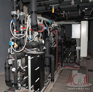
Heating point individual
A thermal installation that deals with or of its individual parts is an individual heating point, or abbreviated ITP. It is intended to provide hot water supply, ventilation and heat to residential buildings, housing and communal services, as well as industrial complexes.
For its operation, it will be necessary to connect to the water and heat system, as well as the power supply necessary to activate the circulation pumping equipment.
A small individual heating point can be used in a single-family house or a small building connected directly to the centralized heating network. Such equipment is designed for space heating and water heating.
A large individual heating point is engaged in the maintenance of large or multi-apartment buildings. Its power ranges from 50 kW to 2 MW.
Main goals
The individual heat point provides the following tasks:
- Accounting for heat and coolant consumption.
- Protection of the heat supply system from an emergency increase in the parameters of the coolant.
- Shutdown of the heat consumption system.
- Uniform distribution of the coolant throughout the heat consumption system.
- Adjustment and control of parameters of the circulating liquid.
- Converting the type of coolant.
Advantages
- High economy.
- Long-term operation of an individual heating point has shown that modern equipment of this type, unlike other manual processes, consumes 30% less
- Operating costs are reduced by about 40-60%.
- The choice of the optimal mode of heat consumption and precise adjustment will reduce the loss of thermal energy by up to 15%.
- Silent operation.
- Compactness.
- The overall dimensions of modern heat points are directly related to the heat load. With compact placement, an individual heating point with a load of up to 2 Gcal / h occupies an area of 25-30 m 2.
- Possibility of location this device in the basement of small-sized premises (both in existing and newly built buildings).
- The work process is fully automated.
- Highly qualified personnel are not required to service this thermal equipment.
- ITP (individual heating point) provides indoor comfort and guarantees effective energy saving.
- The ability to set the mode, focusing on the time of day, the use of the weekend and holiday, as well as carrying out weather compensation.
- Individual production depending on the requirements of the customer.

Thermal energy accounting
The basis of energy saving measures is the metering device. This accounting is required to perform calculations for the amount of consumed thermal energy between the heat supply company and the subscriber. After all, very often the calculated consumption is much higher than the actual one due to the fact that when calculating the load, heat energy suppliers overestimate their values, referring to additional costs. Such situations will be avoided by installing metering devices.
Appointment of metering devices
- Ensuring fair financial settlements between consumers and suppliers of energy resources.
- Documentation of heating system parameters such as pressure, temperature and flow rate.
- Control over the rational use of the energy system.
- Control over the hydraulic and thermal regime of the heat consumption and heat supply system.
The classic scheme of the meter
- Thermal energy counter.
- Pressure gauge.
- Thermometer.
- Thermal converter in the return and supply pipeline.
- Primary flow converter.
- Mesh-magnetic filter.
Service
- Connecting a reader and then taking readings.
- Analysis of errors and finding out the reasons for their occurrence.
- Checking the integrity of seals.
- Analysis of results.
- Checking technological indicators, as well as comparing the readings of thermometers on the supply and return pipelines.
- Adding oil to the sleeves, cleaning the filters, checking the ground contacts.
- Removal of dirt and dust.
- Recommendations for correct operation internal heating networks.
Heating substation scheme
The classic ITP scheme includes the following nodes:
- Entering the heating network.
- Metering device.
- Connecting the ventilation system.
- Heating system connection.
- Hot water connection.
- Coordination of pressures between heat consumption and heat supply systems.
- Make-up of heating and ventilation systems connected according to an independent scheme.

When developing a project for a heating point, the obligatory nodes are:
- Metering device.
- Pressure matching.
- Entering the heating network.
Completion with other nodes, as well as their number is selected depending on the design solution.
Consumption systems
The standard scheme of an individual heat point can have the following systems for providing thermal energy to consumers:
- Heating.
- Hot water supply.
- Heating and hot water supply.
- Heating and ventilation.
ITP for heating
ITP (individual heating point) - an independent scheme, with the installation of a plate heat exchanger, which is designed for 100% load. Installation of the double pump compensating losses of level of pressure is provided. The heating system is fed from the return pipeline of the heating networks.
This heating point can be additionally equipped with a hot water supply unit, a metering device, as well as other necessary units and assemblies.

ITP for hot water supply
ITP (individual heating point) - an independent, parallel and single-stage scheme. The package includes two heat exchangers. lamellar type, the work of each of them is designed for 50% of the load. There is also a group of pumps designed to compensate for pressure drops.
Additionally, the heating point can be equipped with a heating system unit, a metering device and other necessary units and assemblies.
ITP for heating and hot water
IN this case the operation of an individual heating point (ITP) is organized according to an independent scheme. For the heating system, a plate heat exchanger is provided, which is designed for 100% load. The hot water supply scheme is independent, two-stage, with two plate-type heat exchangers. In order to compensate for the decrease in the pressure level, a group of pumps is provided.
The heating system is fed with the help of appropriate pumping equipment from the return pipeline of heating networks. The hot water supply is fed from the cold water supply system.
In addition, ITP (individual heating point) is equipped with a metering device.

ITP for heating, hot water supply and ventilation
The connection of the thermal installation is carried out according to an independent scheme. For heating and ventilation system a plate heat exchanger is used, designed for 100% load. The hot water supply scheme is independent, parallel, single-stage, with two plate heat exchangers, each designed for 50% of the load. The pressure drop is compensated by a group of pumps.
The heating system is fed from the return pipe of the heating networks. The hot water supply is fed from the cold water supply system.
Additionally, an individual heating point in an apartment building can be equipped with a metering device.
Principle of operation
The scheme of the heat point directly depends on the characteristics of the source supplying energy to the ITP, as well as on the characteristics of the consumers it serves. The most common for this thermal installation is a closed hot water supply system with the heating system connected according to an independent circuit.

An individual heating point has the following principle of operation:
- Through the supply pipeline, the coolant enters the ITP, gives off heat to the heaters of the heating and hot water supply systems, and also enters the ventilation system.
- Then the coolant is sent to the return pipeline and flows back through the main network for reuse to the heat generating enterprise.
- A certain amount of coolant can be consumed by consumers. To make up for losses at the heat source, CHPPs and boiler houses are provided with make-up systems, which use the water treatment systems of these enterprises as a heat source.
- Incoming in thermal plant tap water flows through pump equipment cold water systems. Then some of its volume is delivered to consumers, the other is heated in the first stage hot water heater, after which it is sent to the hot water circulation circuit.
- Water in the circulation circuit by means of circulation pumping equipment for hot water supply moves in a circle from the heat point to consumers and back. At the same time, as necessary, consumers take water from the circuit.
- As the fluid circulates around the circuit, it gradually releases its own heat. To maintain the temperature of the coolant at an optimal level, it is regularly heated in the second stage of the hot water heater.
- The heating system is also a closed circuit, along which the coolant moves with the help of circulation pumps from the heat point to consumers and back.
- During operation, coolant leaks from the heating system circuit may occur. The losses are replenished by the ITP replenishment system, which uses primary heating network as a heat source.
Admission to operation
In order to prepare an individual heating point in a house for admission to operation, it is necessary to submit the following list of documents to Energonadzor:
- The current technical conditions for connection and a certificate of their implementation from the energy supply organization.
- Project documentation with all necessary approvals.
- The act of responsibility of the parties for the operation and separation of the balance sheet, drawn up by the consumer and representatives of the energy supply organization.
- The act of readiness for permanent or temporary operation of the subscriber branch of the heating point.
- ITP passport with brief description heating systems.
- Certificate of readiness for operation of the heat energy meter.
- Certificate of conclusion of an agreement with an energy supply organization for heat supply.
- The act of acceptance of the work performed (indicating the license number and the date of its issue) between the consumer and the installation organization.
- persons for the safe operation and good condition of thermal installations and heating networks.
- List of operational and operational-repair responsible persons for the maintenance of heating networks and thermal installations.
- A copy of the welder's certificate.
- Certificates for used electrodes and pipelines.
- Acts for hidden work, an executive diagram of a heat point indicating the numbering of fittings, as well as diagrams of pipelines and valves.
- Act for flushing and pressure testing of systems (heating networks, heating system and hot water supply system).
- Officials and safety precautions.
- Operating Instructions.
- Certificate of admission to the operation of networks and installations.
- Log book for instrumentation, issuance of work permits, operational, accounting for defects identified during the inspection of installations and networks, testing knowledge, as well as briefings.
- Outfit from heating networks for connection.

Safety precautions and operation
The personnel serving the heat point must have the appropriate qualifications, and the responsible persons should also be familiarized with the operating rules, which are stipulated in This is a mandatory principle of an individual heat point approved for operation.
It is forbidden to put the pumping equipment into operation with the shut-off valves at the inlet blocked and in the absence of water in the system.
During operation it is necessary:
- Monitor the pressure readings on the pressure gauges installed on the supply and return pipelines.
- Observe the absence of extraneous noise, and also prevent excessive vibration.
- Control the heating of the electric motor.
Do not use excessive force when manually operating the valve, and do not disassemble the regulators if there is pressure in the system.
Before starting the heating point, it is necessary to flush the heat consumption system and pipelines.
When it comes to the rational use of thermal energy, everyone immediately recalls the crisis and the incredible bills for "fat" provoked by it. In new houses, where engineering solutions are provided that allow you to regulate the consumption of thermal energy in each individual apartment, you can find best option heating or hot water supply (DHW), which will suit the tenant. For old buildings, the situation is much more complicated. Individual heating points become the only reasonable solution to the problem of saving heat for their inhabitants.
Definition of ITP - individual heating point
According to the textbook definition, an ITP is nothing more than a heating point designed to serve the whole building or its individual parts. This dry formulation needs some explanation.
The functions of an individual heating point are to redistribute the energy coming from the network (central heating point or boiler room) between ventilation, hot water and heating systems, in accordance with the needs of the building. This takes into account the specifics of the premises served. Residential, warehouse, basement and other types of them, of course, should differ in temperature conditions and ventilation parameters.
Installation of ITP implies the presence of a separate room. Most often, the equipment is mounted in the basement or technical rooms of high-rise buildings, extensions to apartment buildings or in detached buildings located in close proximity.
Modernization of the building by installing ITP requires significant financial costs. Despite this, the relevance of its implementation is dictated by the advantages that promise undoubted benefits, namely:
- coolant consumption and its parameters are subject to accounting and operational control;
- distribution of the coolant throughout the system depending on the conditions of heat consumption;
- regulation of the coolant flow, in accordance with the requirements that have arisen;
- the possibility of changing the type of coolant;
- increased level of safety in case of accidents and others.
The ability to influence the process of coolant consumption and its energy performance is attractive in itself, not to mention the savings from rational use thermal resources. The one-time costs of ITP equipment will more than pay off in a very modest period of time.
The structure of an ITP depends on which consumption systems it serves. In general, it can be equipped with systems for providing heating, hot water supply, heating and hot water supply, as well as heating, hot water supply and ventilation. Therefore, the ITP must include the following devices:
- heat exchangers for the transfer of thermal energy;
- valves of locking and regulating action;
- instruments for monitoring and measuring parameters;
- pump equipment;
- control panels and controllers.
Here are only the devices that are present on all ITPs, although each specific option may have additional nodes. The source of cold water supply is usually located in the same room, for example.
The scheme of the heating substation is built using a plate heat exchanger and is completely independent. To maintain the pressure at the required level, a dual pump is installed. There is a simple way to "re-equip" the circuit with a hot water supply system and other nodes and units, including metering devices.
The operation of the ITP for hot water supply implies the inclusion in the scheme of plate heat exchangers that operate only on the load on the hot water supply. Pressure drops in this case are compensated by a group of pumps.
In the case of organizing systems for heating and hot water supply, the above schemes are combined. Plate heat exchangers for heating work together with a two-stage DHW circuit, and the heating system is replenished from the return pipeline of the heating network by means of appropriate pumps. The cold water supply network is the feeding source for the DHW system.
If it is necessary to connect a ventilation system to the ITP, then it is equipped with another plate heat exchanger connected to it. Heating and hot water continue to work according to the previously described principle, and the ventilation circuit is connected in the same way as a heating circuit with the addition of the necessary instrumentation.
Individual heating point. Principle of operation
The central heat point, which is the source of the heat carrier, supplies hot water to the inlet of the individual heat point through the pipeline. Moreover, this liquid in no way enters any of the building systems. Both for heating and for heating water in the DHW system, as well as for ventilation, only the temperature of the supplied coolant is used. Energy is transferred to the systems in plate-type heat exchangers.
The temperature is transferred by the main coolant to the water taken from the cold water supply system. So, the cycle of movement of the coolant begins in the heat exchanger, passes through the path of the corresponding system, giving off heat, and returns through the return main water supply for further use to the enterprise providing heat supply (boiler room). The part of the cycle that provides for the release of heat heats the dwellings and makes the water in the taps hot.
Cold water enters the heaters from the cold water supply system. For this, a system of pumps is used to maintain the required level of pressure in the systems. Pumps and additional devices are necessary to reduce or increase the water pressure from the supply line to an acceptable level, as well as its stabilization in the building systems.
Benefits of using ITP
The four-pipe heat supply system from the central heating point, which was previously used quite often, has a lot of disadvantages that are absent from the ITP. In addition, the latter has a number of very significant advantages over its competitor, namely:
- efficiency due to a significant (up to 30%) reduction in heat consumption;
- the availability of devices simplifies the control of both the flow of the coolant and the quantitative indicators of thermal energy;
- the possibility of flexible and prompt influence on heat consumption by optimizing the mode of its consumption, depending on the weather, for example;
- ease of installation and rather modest overall dimensions of the device, allowing it to be placed in small rooms;
- reliability and stability of the ITP, as well as favorable influence on the same characteristics of the serviced systems.
This list can be continued indefinitely. It reflects only the main, lying on the surface, the benefits obtained by using ITP. It can be added, for example, the ability to automate the management of ITP. In this case, its economic and operational performance becomes even more attractive to the consumer.
The most significant drawback of the ITP, apart from transportation costs and the cost of loading and unloading activities, is the need to settle all sorts of formalities. Obtaining appropriate permits and approvals can be considered a very serious task.
In fact, only a specialized organization can solve such problems.
Stages of installation of a heat point
It is clear that one decision, albeit a collective one, based on the opinion of all the residents of the house, is not enough. Briefly, the procedure for equipping the object, apartment building, for example, can be described as follows:
- in fact, a positive decision of the residents;
- application to the heat supply organization for the development of technical specifications;
- obtaining technical specifications;
- pre-project survey of the object, to determine the condition and composition of the existing equipment;
- development of the project with its subsequent approval;
- conclusion of an agreement;
- project implementation and commissioning tests.
The algorithm may seem, at first glance, rather complicated. In fact, all the work from decision to commissioning can be done in less than two months. All worries should be placed on the shoulders of a responsible company that specializes in providing this kind of service and has a positive reputation. Thankfully, there are plenty of them now. It remains only to wait for the result.
Thermal point
Thermal point(TP) - a complex of devices located in a separate room, consisting of elements of thermal power plants that ensure the connection of these plants to the heating network, their performance, control of heat consumption modes, transformation, regulation of coolant parameters and distribution of coolant by type of consumption.
Substation and attached building
Purpose
The main tasks of the TP are:
- Converting the type of coolant
- Control and regulation of coolant parameters
- Distribution of heat carrier by heat consumption systems
- Shutdown of heat consumption systems
- Protection of heat consumption systems from an emergency increase in the parameters of the coolant
Types of heat points
TPs differ in the number and type of heat consumption systems connected to them, the individual characteristics of which determine thermal scheme and characteristics of the TP equipment, as well as by the type of installation and features of the equipment placement in the TP room. There are the following types of TP:
- Individual heating point(AND SO ON). It is used to serve one consumer (building or part of it). As a rule, it is located in the basement or technical room of the building, however, due to the characteristics of the serviced building, it can be placed in a separate building.
- Central heating point(CTP). It is used to serve a group of consumers (buildings, industrial facilities). Most often located in a separate building, but can be placed in the basement or technical room of one of the buildings.
- Block heat point(BTP). It is manufactured in the factory and supplied for installation in the form of ready-made blocks. It may consist of one or more blocks. The equipment of the blocks is mounted very compactly, as a rule, on one frame. Usually used when you need to save space, in cramped conditions. By the nature and number of connected consumers, the BTP can refer to both ITP and CHP.
Heat sources and thermal energy transport systems
The source of heat for TP is heat generating enterprises (boiler houses, combined heat and power plants). TP is connected to sources and consumers of heat through heating networks. Thermal networks are divided into primary main heating networks connecting TP with heat generating enterprises, and secondary(distributing) heating networks connecting the transformer substation with end users. The section of the heating network that directly connects the heating substation and the main heating networks is called thermal input.
The main heat networks, as a rule, have a large length (the distance from the heat source is up to 10 km or more). For the construction of trunk networks, steel pipelines with a diameter of up to 1400 mm are used. In conditions where there are several heat generating enterprises, loopbacks are made on the main heat pipelines, uniting them into one network. This allows you to increase the reliability of the supply of heat points, and, ultimately, consumers with heat. For example, in cities, in the event of an accident on a highway or a local boiler house, heat supply can be taken over by the boiler house of a neighboring district. Also, in some cases, the common network makes it possible to distribute the load between heat generating enterprises. Specially prepared water is used as a heat carrier in main heating networks. During preparation, the indicators of carbonate hardness, oxygen content, iron content and pH are normalized in it. Unprepared for use in heating networks (including tap water, drinking water) is unsuitable for use as a heat carrier, since when high temperatures ah, due to the formation of deposits and corrosion, will cause increased wear of pipelines and equipment. The design of the TP prevents relatively rigid tap water to the main heating systems.
Secondary heating networks have a relatively small length (removal of TS from the consumer up to 500 meters) and in urban conditions are limited to one or a couple of quarters. Diameters of pipelines of secondary networks, as a rule, are in the range from 50 to 150 mm. During the construction of secondary heating networks, both steel and polymer pipelines can be used. The use of polymer pipelines is most preferable, especially for hot water systems, since hard tap water, combined with elevated temperatures, leads to intense corrosion and premature failure of steel pipelines. In the case of an individual heating point, there may be no secondary heating networks.
Water supply systems serve as a source of water for cold and hot water supply systems.
Thermal energy consumption systems
In a typical TP, there are the following systems for supplying consumers with thermal energy:
Schematic diagram of a heat point
The TP scheme depends, on the one hand, on the characteristics of thermal energy consumers served by the heating point, on the other hand, on the characteristics of the source supplying the TP with thermal energy. Further, as the most common, TP is considered with a closed hot water supply system and an independent scheme for connecting the heating system.

Schematic diagram of a heat point
The coolant entering the TP by supply pipeline heat input, gives off its heat in the heaters of hot water and heating systems, and also enters the consumer ventilation system, after which it returns to return pipeline thermal input and is sent back to the heat generating enterprise for reuse through the main networks. Part of the coolant can be consumed by the consumer. To make up for losses in primary heat networks at boiler houses and CHPPs, there are make-up systems, the coolant sources for which are water treatment systems these enterprises.
Tap water entering the TP passes through cold water pumps, after which part of the cold water is sent to consumers, and the other part is heated in the heater first stage DHW and enters the circulation circuit of the DHW system. In the circulation circuit, water, using hot water circulation pumps, moves in a circle from the transformer substation to consumers and back, and consumers take water from the circuit as needed. When circulating around the circuit, the water gradually gives up its heat and in order to maintain the water temperature at a given level, it is constantly heated in the heater second stage DHW.
The heating system is also a closed circuit, along which the coolant moves with the help of heating circulation pumps from the heating substation to the building heating system and back. During operation, leakage of the coolant from the circuit of the heating system may occur. To make up for losses make-up system a heat point using primary heating networks as a heat carrier source.
Notes
Literature
- Sokolov E.Ya. Heat supply and heat networks: a textbook for universities. - 8th ed., stereo. / E.Ya. Sokolov. - M.: MPEI Publishing House, 2006. - 472 p.: ill.
- SNiP 2.04.07-86 Heating networks (ed. 1994 with change 1 BST 3-94, change 2, adopted by the Decree of the Gosstroy of Russia dated 12.10.2001 N116 and with the exception of section 8 and applications 12-19). Thermal points.
- SP 41-101-95 “Codes of rules for design and construction. Design of thermal points.
| Energy structure by products and industries |
||||||||||||||||||||||||||||
|---|---|---|---|---|---|---|---|---|---|---|---|---|---|---|---|---|---|---|---|---|---|---|---|---|---|---|---|---|
| Power industry: electricity |
|
 |
||||||||||||||||||||||||||
| Heat supply: heat energy |
||||||||||||||||||||||||||||
| decentralized | ||||||||||||||||||||||||||||
| Heating network | ||||||||||||||||||||||||||||
industry :
fuel
| organic |
|
At district heating heating point may be local - individual(ITP) for heat-consuming systems of a specific building and group - central(CTP) for systems of a group of buildings. ITP is located in a special room of the building, the central heating station is most often a separate one-story building. The design of heat points is carried out in accordance with regulatory rules.
The role of a heat generator with an independent scheme for connecting heat-consuming systems to an external heating network is performed by a water heat exchanger.
Currently, so-called high-speed heat exchangers are used. various types. The shell and tube water heat exchanger consists of standard sections up to 4 m long. Each section is steel pipe up to 300 mm in diameter, inside which several brass tubes are placed. In an independent scheme of a heating or ventilation system, heating water from an external heat pipe is passed through brass tubes, heated - by counterflow in the annular space, in the hot water supply system, heated tap water is passed through the tubes, and heating water from the heating network - in the annulus. A more advanced and much more compact plate heat exchanger is assembled from a certain number of profiled steel plates. The heating and heated water flows between the plates countercurrently or crosswise. The length and number of sections of a shell-and-tube heat exchanger or the dimensions and number of plates in a plate heat exchanger is determined by a special thermal calculation.
For heating water in hot water supply systems, especially in an individual residential building, not a high-speed, but a capacitive water heater is more suitable. Its volume is determined based on the estimated number of simultaneously operating water points and the estimated individual characteristics of water consumption in the house.
Common to all schemes is the use of a pump to artificially stimulate the movement of water in heat-consuming systems. In dependent circuits, the pump is placed at a thermal station, and it creates the pressure necessary for water circulation, both in external heat pipelines and in local heat-consuming systems.
A pump operating in closed rings of systems filled with water does not lift, but only moves water, creating a circulation, and therefore is called a circulation pump. Unlike a circulation pump, a pump in a water supply system moves water, raising it to the points of analysis. When used in this way, the pump is called a booster pump.
The circulation pump does not participate in the processes of filling and compensating for the loss (leakage) of water in the heating system. Filling occurs under the influence of pressure in the external heat pipes, in the water supply system or, if this pressure is not enough, using a special make-up pump.
Until recently, the circulation pump was included, as a rule, in the return line of the heating system to increase the service life of parts interacting with hot water. In general, to create water circulation in closed rings, the location of the circulation pump is indifferent. If it is necessary to slightly reduce the hydraulic pressure in the heat exchanger or boiler, the pump can also be included in the supply line of the heating system, if its design is designed to move more than hot water. All modern pumps have this property and are most often installed after the heat generator (heat exchanger). Electric power the circulation pump is determined by the amount of water being moved and the pressure developed at the same time.
IN engineering systems ah, as a rule, special foundationless circulation pumps, moving a significant amount of water and developing a relatively small pressure. These are silent pumps connected in a single unit with electric motors and fixed directly on the pipes. The system includes two identical pumps operating alternately: when one of them is operating, the second is in reserve. Shut-off valves(valves or cocks) before and after both pumps (active and inactive) are constantly open, especially if their automatic switching is provided. check valve in the circuit prevents the circulation of water through an inactive pump. Easily installed foundationless pumps are sometimes installed one at a time in systems. At the same time, the reserve pump is stored in a warehouse.
The decrease in water temperature in the dependent circuit with mixing to the permissible level occurs when high-temperature water is mixed with return (cooled to a predetermined temperature) water of the local system. The coolant temperature is lowered by mixing return water from engineering systems using a mixing apparatus - a pump or a water jet elevator. The pump mixing plant has an advantage over the elevator one. Its efficiency is higher; in case of emergency damage to external heat pipelines, it is possible, as with an independent connection scheme, to maintain water circulation in the systems. The mixing pump can be used in systems with significant hydraulic resistance, while when using an elevator, pressure losses in the heat-consuming system should be relatively small. Water jet elevators received wide use thanks to its smooth and quiet operation.
The internal space of all elements of heat-consuming systems (pipes, heating appliances, fittings, equipment, etc.) is filled with water. The volume of water during the operation of the systems undergoes changes: when the water temperature rises, it increases, and when the temperature drops, it decreases. Accordingly, the internal hydrostatic pressure changes. These changes should not affect the performance of the systems and, above all, should not lead to exceeding the ultimate strength of any of their elements. Therefore, the system is introduced additional element- expansion tank.
The expansion tank can be open, vented to the atmosphere, and closed, under variable, but strictly limited overpressure. The main purpose of the expansion tank is to receive the increase in the volume of water in the system, which is formed when it is heated. At the same time, a certain hydraulic pressure is maintained in the system. In addition, the tank is designed to replenish the loss of water in the system in case of a small leak and when its temperature drops, to signal the water level in the system and control the operation of make-up devices. Through an open tank, water is removed into the drain when the system overflows. In some cases, an open tank can serve as an air vent from the system.
An open expansion tank is placed above the top point of the system (at a distance of at least 1 m) in attic or in stairwell and covered with thermal insulation. Sometimes (for example, in the absence of an attic), an uninsulated tank is installed in a special insulated box (booth) on the roof of the building.
Modern design closed expansion tank is a steel cylindrical vessel, divided into two parts by a rubber membrane. One part is designed for system water, the second is factory filled with an inert gas (usually nitrogen) under pressure. The tank can be installed directly on the floor of a boiler room or heating point, as well as fixed on the wall (for example, in cramped conditions in the room).
In large heat-consuming systems of a group of buildings expansion tanks are not installed, and the hydraulic pressure is regulated by permanently operating booster pumps. These pumps also compensate for water losses that normally occur through leaky pipe connections, fittings, appliances, and other system locations.
In addition to the equipment discussed above, the boiler house or heating point houses automatic control devices, shut-off and control valves and instrumentation, which ensure the current operation of the heat supply system. The fittings used in this case, as well as the material and methods for laying heat pipes, are discussed in the "Heating of buildings" section.
The correct functioning of the heat point equipment determines the efficiency of using both the heat supplied to the consumer and the coolant itself. The heating point is a legal boundary, which implies the need to equip it with a set of control and measuring instruments that allow determining the mutual responsibility of the parties. The schemes and equipment of heat points must be determined in accordance not only with the technical characteristics of local heat consumption systems, but also necessarily with the characteristics of the external heat network, its mode of operation and the heat source.
Section 2 discusses connection schemes for all three main types of local systems. They were considered separately, i.e., it was considered that they were connected, as it were, to a common collector, the coolant pressure in which is constant and does not depend on the flow rate. The total flow rate of the coolant in the collector in this case is equal to the sum of the flow rates in the branches.
However, heat points are not connected to the heat source collector, but to the heat network, and in this case, a change in the coolant flow in one of the systems will inevitably affect the coolant flow in the other.
Fig.4.35. Heat carrier flow charts:A - when consumers are connected directly to the heat source collector; b - when connecting consumers to the heating network
On fig. 4.35 graphically shows the change in coolant flow rates in both cases: in the diagram of fig. 4.35 A heating and hot water supply systems are connected to the heat source collectors separately, in the diagram of fig. 4.35,b the same systems (and with the same calculated flow rate of the coolant) are connected to an external heating network with significant pressure losses. If in the first case the total flow rate of the coolant grows synchronously with the flow rate for hot water supply (modes I, II, III), then in the second, although there is an increase in the flow rate of the coolant, the flow rate for heating is automatically reduced at the same time, as a result of which the total flow rate of the coolant (in this example) is when applying the scheme of Fig. 4.35, b 80% of the flow rate when applying the scheme of fig. 4.35 a. The degree of reduction in water flow determines the ratio of available pressures: the larger the ratio, the greater the reduction in total flow.
The main heat networks are calculated for the average daily heat load, which significantly reduces their diameters, and, consequently, the cost of funds and metal. When using increased water temperature charts in networks, it is also possible to further reduce the estimated water consumption in the heating network and calculate its diameters only for the heating load and supply ventilation.
The maximum hot water supply can be covered by hot water accumulators or by using the storage capacity of heated buildings. Since the use of batteries inevitably causes additional capital and operating costs, their use is still limited. Nevertheless, in some cases, the use of large batteries in networks and at group heating points (GTPs) can be effective.
When using the storage capacity of heated buildings, there are fluctuations in air temperature in rooms (apartments). It is necessary that these fluctuations do not exceed the permissible limit, which can be taken, for example, +0.5°C. The temperature regime of the premises is determined by a number of factors and therefore it is difficult to calculate. The most reliable in this case is the experimental method. In conditions middle lane RF long-term operation shows the possibility of using this method of maximum coverage for the vast majority of operated residential buildings.
The actual use of the storage capacity of heated (mainly residential) buildings began with the appearance of the first hot water heaters in heating networks. So, the adjustment of the heat point with a parallel scheme for switching on hot water heaters (Fig. 4.36) was carried out in such a way that during the hours of maximum water intake, some part of the network water was not supplied to the heating system. Thermal points operate on the same principle with open water intake. Both with an open and a closed heating system, the greatest reduction in consumption is in heating system takes place at a network water temperature of 70 °С (60 °С) and the smallest (zero) - at 150 °С.
Rice. 4.36. Scheme of a heating point of a residential building with a parallel connection of a hot water heater:

1 - hot water heater; 2 - elevator; 3 4 - circulation pump; 5 - temperature controller from the outdoor air temperature sensor
The possibility of organized and pre-calculated use of the storage capacity of residential buildings is implemented in the scheme of a heating point with the so-called upstream hot water heater (Fig. 4.37).
Rice. 4.37. Scheme of a heating point of a residential building with an upstream hot water heater:

1 - heater; 2 - elevator; 3 - water temperature controller; 4 - flow regulator; 5 - circulation pump
The advantage of the upstream scheme is the possibility of operation of the heating point of a residential building (with heating schedule in the heating network) on constant expense coolant during the entire heating season, which makes the hydraulic regime of the heating network stable.
In the absence of automatic control in heating points, the stability of the hydraulic regime was a convincing argument in favor of using a two-stage sequential scheme for switching on hot water heaters. The possibilities of using this scheme (Fig. 4.38) in comparison with the upstream one increase due to covering a certain share of the hot water supply load by using the heat of the return water. However, the use of this scheme is mainly associated with the introduction of the so-called increased temperature schedule in heat networks, with the help of which an approximate constancy of coolant flow rates at a heat (for example, for a residential building) point can be achieved.
Rice. 4.38. Scheme of a heating point of a residential building with a two-stage serial connection of hot water heaters:
1,2 - 3 - elevator; 4 - water temperature controller; 5 - flow regulator; 6 - jumper for switching to mixed circuit; 7 - circulation pump; 8 - mixing pump
Both in the scheme with a pre-heater and in the two-stage scheme with sequential connection of heaters, there is a close relationship between the release of heat for heating and hot water supply, and priority is usually given to the second.
More versatile in this respect is the two-stage mixed scheme (Fig. 4.39), which can be used both with normal and increased heating schedules and for all consumers, regardless of the ratio of hot water and heating loads. A mandatory element of both schemes are mixing pumps.
Rice. 4.39. Scheme of a heating point of a residential building with a two-stage mixed inclusion of hot water heaters:
1,2 - heaters of the first and second stages; 3 - elevator; 4 - water temperature controller; 5 - circulation pump; 6 - mixing pump; 7 - temperature controller
The minimum temperature of the supplied water in a heat network with a mixed heat load is about 70 °C, which requires limiting the supply of coolant for heating during periods of high outdoor temperatures. In the conditions of the central zone of the Russian Federation, these periods are quite long (up to 1000 hours or more) and the excess heat consumption for heating (in relation to the annual one) can reach up to 3% or more because of this. Because modern systems heating systems are quite sensitive to changes in the temperature-hydraulic regime, then in order to eliminate excess heat consumption and maintain normal sanitary conditions in heated rooms, it is necessary to supplement all the mentioned schemes of thermal points with devices for controlling the temperature of the water entering the heating systems by installing a mixing pump, which is usually used in group heating points. In local heating substations, in the absence of silent pumps, an elevator with an adjustable nozzle can also be used as an intermediate solution. In this case, it should be taken into account that such a solution is unacceptable for a two-stage sequential scheme. The need to install mixing pumps is eliminated when heating systems are connected through heaters, since in this case their role is played by circulation pumps that ensure a constant water flow in the heating network.
When designing schemes for heating points in residential areas with a closed heat supply system, the main issue is the choice of a scheme for connecting hot water heaters. The selected scheme determines the estimated flow rates of the coolant, the control mode, etc.
The choice of the connection scheme is primarily determined by the accepted temperature regime of the heating network. When the heat network is operating according to the heating schedule, the choice of connection scheme should be made on the basis of a technical and economic calculation - by comparing parallel and mixed schemes.
A mixed scheme can provide more low temperature return water from the heat point as a whole compared to the parallel one, which, in addition to reducing the estimated water consumption for the heat network, ensures more economical generation of electricity at the CHPP. Based on this, in the practice of designing for heat supply from a CHP (as well as in the joint operation of boiler houses with a CHP), preference is given to a mixed scheme for the heating temperature curve. With short heating networks from boiler houses (and therefore relatively cheap), the results of a technical and economic comparison may be different, i.e., in favor of using a simpler scheme.
At elevated temperatures in closed systems heat supply, the connection scheme can be mixed or sequential two-stage.
A comparison made by various organizations on examples of automation of central heating points shows that both schemes under conditions normal operation sources of heat supply are approximately equally economical.
A small advantage of the sequential scheme is the possibility of working without a mixing pump for 75% of the duration of the heating season, which previously gave some justification to abandon the pumps; with a mixed circuit, the pump must work all season.
The advantage of a mixed circuit is the possibility of a complete automatic shutdown of heating systems, which cannot be obtained in a sequential circuit, since water from the second stage heater enters the heating system. Both of these circumstances are not decisive. An important indicator of schemes is their work in critical situations.
Such situations can be a decrease in the temperature of the water in the CHPP against the schedule (for example, due to a temporary lack of fuel) or damage to one of the sections of the main heating network in the presence of reserving jumpers.
In the first case, circuits can react in approximately the same way, in the second - in different ways. There is a possibility of 100% redundancy of consumers up to t n = -15 °С without increasing the diameters of heat mains and jumpers between them. To do this, when the heat carrier supply to the CHP is reduced, the temperature of the supplied water simultaneously increases accordingly. Automated mixed circuits (with the obligatory presence of mixing pumps) will react to this by reducing the consumption of network water, which will ensure the restoration of the normal hydraulic regime throughout the entire network. Such compensation of one parameter by another is also useful in other cases, since it allows, within certain limits, to carry out, for example, repair work on heating mains in heating season, as well as to localize known inconsistencies in the temperature of the supplied water to consumers located at different distances from the CHPP.
If the automation of regulation of circuits with sequential switching on of hot water heaters provides for the constancy of the coolant flow from the heating network, the possibility of compensating the coolant flow with its temperature in this case is excluded. It is not necessary to prove the whole expediency (in design, installation and especially in operation) of using a uniform connection scheme. From this point of view undoubted advantage has a two-stage mixed circuit, which can be used regardless of the temperature schedule in the heating network and the ratio of hot water and heating loads.
Rice. 4.40. Scheme of a heating point of a residential building with an open heat supply system:

1 - regulator (mixer) of water temperature; 2 - elevator; 3 - check valve; 4 - throttle washer
Connection schemes for residential buildings with an open heat supply system are much simpler than those described (Fig. 4.40). The economical and reliable operation of such points can only be ensured if there is and reliable operation automatic water temperature controller, manual switching of consumers to the supply or return line does not provide required temperature water. In addition, the hot water supply system, connected to the supply line and disconnected from the return line, operates under the pressure of the supply heat pipe. The above considerations on the choice of schemes of heat points equally apply both to local heat points (LHP) in buildings and to group ones that can provide heat supply to entire microdistricts.
The greater the power of the heat source and the radius of action of heat networks, the more complex the MTP schemes should become fundamentally, since absolute pressures increase, the hydraulic regime becomes more complicated, and transport delay begins to affect. So, in MTP schemes, it becomes necessary to use pumps, protective equipment and complex automatic control equipment. All this not only increases the cost of the construction of ITPs, but also complicates their maintenance. The most rational way to simplify the MTP schemes is the construction of group heating points (in the form of GTP), in which additional complex equipment and devices should be placed. This method is most applicable in residential areas in which the characteristics of heating and hot water supply systems and, therefore, MTP schemes are of the same type.