Do-it-yourself induction heater for hardening metal. How to make an induction heater with your own hands according to the scheme. There are certain conditions for the organization of work
Induction heaters work on the principle of “getting current from magnetism”. In a special coil, a high-power alternating magnetic field is generated, which generates eddy electric currents in a closed conductor.
A closed conductor in induction cookers is metal utensils, which are heated by eddy electric currents. In general, the principle of operation of such devices is not complicated, and with little knowledge in physics and electrical engineering, it will not be difficult to assemble an induction heater with your own hands.
The following devices can be made independently:
- Devices for heating in a heating boiler.
- Mini ovens for melting metals.
- Plates for cooking food.
Do-it-yourself induction cooker must be made in compliance with all norms and rules for the operation of these devices. If electromagnetic radiation dangerous for humans is emitted outside the case in the lateral directions, then it is strictly forbidden to use such a device.
In addition, a great difficulty in the design of the stove lies in the selection of material for the base of the hob, which must meet the following requirements:
- Ideal for conducting electromagnetic radiation.
- Not conductive.
- Withstand high temperature stress.
In domestic induction hobs, expensive ceramics are used, when made at home induction cooker, to find a worthy alternative to such material is quite difficult. Therefore, to begin with, you should design something simpler, for example, an induction furnace for hardening metals.
Manufacturing instructions
Blueprints
 Figure 1. Electrical diagram of the induction heater
  Figure 2. Device.
  Figure 3. Scheme of a simple induction heater
 For the manufacture of the furnace you will need the following materials and tools:
- solder;
- textolite board.
- mini drill.
- radioelements.
- thermal paste.
- chemical reagents for board etching.
Additional materials and their features:
- To make a coil, which will emit an alternating magnetic field necessary for heating, it is necessary to prepare a segment copper tube 8 mm in diameter and 800 mm long.
- Powerful power transistors are the most expensive part of a homemade induction installation. To mount the frequency generator circuit, it is necessary to prepare 2 such elements. For these purposes, transistors of brands are suitable: IRFP-150; IRFP-260; IRFP-460. In the manufacture of the circuit, 2 identical of the listed field-effect transistors are used.
- For the manufacture of an oscillatory circuit you will need ceramic capacitors with a capacity of 0.1 mF and an operating voltage of 1600 V. In order for a high-power alternating current to form in the coil, 7 such capacitors are required.
- During the operation of such an induction device, field-effect transistors will get very hot and if radiators from aluminum alloy, then after a few seconds of operation at maximum power, these elements will fail. Transistors should be placed on heat sinks through a thin layer of thermal paste, otherwise the efficiency of such cooling will be minimal.
- Diodes, which are used in an induction heater, must be of ultra-fast action. The most suitable for this circuit, diodes: MUR-460; UV-4007; HER-307.
- Resistors used in circuit 3: 10 kOhm with a power of 0.25 W - 2 pcs. and 440 ohm power - 2 watts. Zener diodes: 2 pcs. with an operating voltage of 15 V. The power of the zener diodes must be at least 2 watts. A choke for connecting to the power outputs of the coil is used with induction.
- To power the entire device, you will need a power supply unit with a capacity of up to 500. W. and voltage 12 - 40 V. You can power this device from a car battery, but you will not be able to get the highest power readings at this voltage.
 The very process of manufacturing an electronic generator and coil takes a little time and is carried out in the following sequence:
- From a copper pipe a spiral with a diameter of 4 cm is made. To make a spiral, a copper tube should be wound onto a rod with flat surface 4 cm in diameter. The spiral should have 7 turns, which should not touch. Mounting rings are soldered to the 2 ends of the tube for connection to the transistor radiators.
- The printed circuit board is made according to the scheme. If it is possible to supply polypropylene capacitors, then due to the fact that such elements have minimal losses and stable operation at large amplitudes of voltage fluctuations, the device will work much more stable. The capacitors in the circuit are installed in parallel, forming an oscillatory circuit with a copper coil.
- Metal heating occurs inside the coil, after the circuit is connected to a power supply or battery. When heating metal, it is necessary to ensure that there is no short circuit spring windings. If you touch the heated metal 2 turns of the coil at the same time, then the transistors fail instantly.
Nuances

- When conducting experiments on heating and hardening metals, inside the induction coil the temperature can be significant and amounts to 100 degrees Celsius. This heating effect can be used to heat domestic water or to heat a house.
- Scheme of the heater discussed above (Figure 3), at maximum load it is able to provide the radiation of magnetic energy inside the coil equal to 500 watts. This power is not enough to heat large volume water, and the building induction coil high power will require the manufacture of a circuit in which it will be necessary to use very expensive radio elements.
- A budget solution for organizing induction heating of a liquid, is the use of several devices described above, arranged in series. In this case, the spirals must be on the same line and not have a common metal conductor.
- Aspipe is used of stainless steel 20 mm in diameter. Several induction spirals are “strung” onto the pipe, so that the heat exchanger is in the middle of the spiral and does not come into contact with its turns. With the simultaneous inclusion of 4 such devices, the heating power will be about 2 kW, which is already enough for flow heating liquids with a small circulation of water, up to values that allow the use this design in supply warm water small house.
- If you connect such a heating element to a well-insulated tank, which will be located above the heater, the result will be a boiler system in which the heating of the liquid will be carried out inside the stainless pipe, the heated water will rise up, and a colder liquid will take its place.
- If the area of the house is significant, the number of induction coils can be increased up to 10 pieces.
- The power of such a boiler can be easily adjusted by turning off or on the spirals. The more sections that are simultaneously turned on, the greater the power of the heating device operating in this way will be.
- To power such a module, you need a powerful power supply. If there is an inverter welding machine direct current, then it is possible to make a voltage converter of the required power from it.
- Due to the fact that the system works at a constant electric current , which does not exceed 40 V, the operation of such a device is relatively safe, the main thing is to provide a fuse box in the generator power circuit, which, in the event of a short circuit, will de-energize the system, thereby eliminating the possibility of a fire.
- It is possible to organize “free” heating of the house in this way, subject to installation for power induction devices batteries, which will be charged by solar and wind energy.
- Batteries should be combined in sections of 2, connected in series. As a result, the supply voltage with such a connection will be at least 24 V., which will ensure the operation of the boiler at high power. In addition, series connection will reduce the current in the circuit and increase the battery life.

- Exploitation homemade devices induction heating, does not always allow to exclude the spread of harmful to humans electromagnetic radiation, therefore, the induction boiler should be installed in a non-residential area and shielded with galvanized steel.
- Mandatory when working with electricity safety regulations must be followed and, especially for 220 V AC networks.
- As an experiment can be made hob for cooking food according to the scheme indicated in the article, but it is not recommended to constantly operate this device due to imperfections self-manufacturing shielding this device, because of this, exposure to the human body of harmful electromagnetic radiation that can adversely affect health is possible.
When a person faces the need to heat a metal object, fire always comes to mind. Fire is an old fashioned, inefficient and slow way to heat metal. He spends the lion's share of energy on heat, and smoke always comes from the fire. It would be great if all these problems could be avoided.

Today I will show you how to assemble an induction heater with your own hands with a ZVS driver. This fixture heats most metals with a ZVS driver and electromagnetism. Such a heater is highly efficient, does not produce smoke, and heating such small metal products like, say, a paper clip is a matter of seconds. The video shows the heater in action, but the instructions are different.
Step 1: How it works


Many of you are now wondering - what is this ZVS driver? It is a highly efficient transformer capable of creating a powerful electromagnetic field that heats the metal, the basis of our heater.
To make it clear how our device works, I will talk about key points. First important point- 24V power supply. The voltage should be 24V at a maximum current of 10A. I will have two lead acid batteries connected in series. They power the ZVS driver board. The transformer gives a steady current to the spiral, inside which is placed the object that needs to be heated. A constant change in the direction of the current creates an alternating magnetic field. It creates eddy currents inside the metal, mostly of high frequency. Due to these currents and the low resistance of the metal, heat is generated. According to Ohm's law, the current strength, transformed into heat, in a circuit with active resistance, will be P \u003d I ^ 2 * R.
The metal that makes up the object you want to heat is very important. Iron-based alloys have higher magnetic permeability, they can use more energy magnetic field. Because of this, they heat up faster. Aluminum has a low magnetic permeability and heats up, respectively, longer. And objects with high resistance and low magnetic permeability, such as a finger, will not heat up at all. The resistance of the material is very important. The higher the resistance, the weaker the current will pass through the material, and the less heat will be generated. The lower the resistance, the stronger the current will be, and according to Ohm's law, there will be less voltage loss. It's a little tricky, but due to the relationship between resistance and power output, maximum power output is achieved when the resistance is 0.
The ZVS transformer is the most complicated part of the device, I will explain how it works. When the current is turned on, it goes through two induction chokes to both ends of the coil. Chokes are needed to make sure that the device does not give out too much current. Next, the current goes through 2 470 Ohm resistors to the gates of the MIS transistors.
Because perfect components don't exist, one transistor will turn on before the other. When this happens, it takes over all the incoming current from the second transistor. He will also short out second to ground. Because of this, not only will the current flow through the coil to the ground, but the gate of the second transistor will also be discharged through the fast diode, thereby blocking it. Due to the fact that a capacitor is connected in parallel with the coil, an oscillatory circuit is created. Due to the resonance that has arisen, the current will change its direction, the voltage will drop to 0V. At this moment, the gate of the first transistor is discharged through the diode to the gate of the second transistor, blocking it. This cycle is repeated thousands of times per second.
The 10K resistor is designed to reduce excess transistor gate charge by acting as a capacitor, and the zener diode must keep the gate voltage of the transistors at 12V or lower so they don't explode. This transformer high frequency voltage converter allows metal objects to heat up.
It's time to assemble the heater.
Step 2: Materials


Few materials are needed to assemble the heater, and most of them, fortunately, can be found for free. If you see a cathode ray tube lying around just like that, go and pick it up. It contains most of the parts needed for the heater. If you want better parts, buy them from an electrical parts store.
You will need:
Step 3: Tools

For this project you will need:
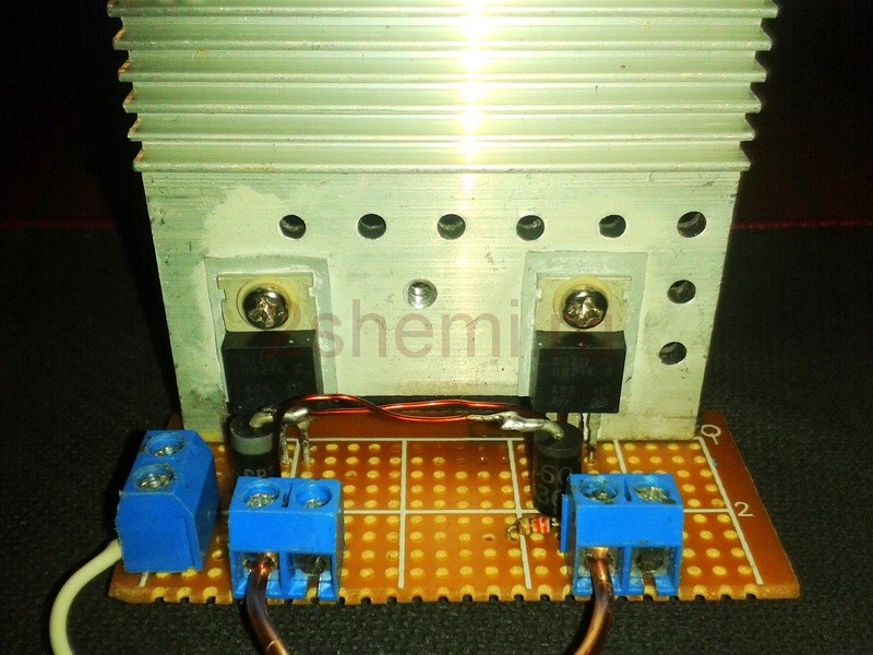
Step 4: FET Cooling

In this device, the transistors turn off at a voltage of 0 V, and they do not heat up very much. But if you want the heater to run longer than one minute, you need to remove heat from the transistors. I made both transistors one common heat sink. Make sure that the metal gates do not touch the absorber, otherwise the MOS transistors will short out and explode. I used a computer heatsink and it already had a stripe on it silicone sealant. To check the insulation, touch the middle leg of each MIS transistor (gate) with a multimeter, if the multimeter beeps, then the transistors are not isolated.
Step 5: Capacitor Bank

Capacitors get very hot due to the current constantly passing through them. Our heater needs a 0.47uF capacitor. Therefore, we need to combine all the capacitors into a block, thus we will get the required capacitance, and the heat dissipation area will increase. The voltage rating of the capacitors must be higher than 400V to account for inductive voltage peaks in the resonant circuit. I made two copper wire rings, to which I soldered 10 0.047 uF capacitors in parallel to each other. Thus, I got a capacitor bank with a total capacity of 0.47 microfarads with excellent air cooling. I will install it parallel to the working spiral.
Step 6: Working Spiral


This is the part of the device in which the magnetic field is created. The spiral is made of copper wire - it is very important that copper is used. At first I used a steel coil for heating, and the device did not work very well. Without a workload, it consumed 14 A! For comparison, after replacing the coil with copper, the device only consumed 3 A. I think that the steel coil had eddy currents due to the iron content, and it was also subjected to induction heating. I'm not sure that this is the reason, but this explanation seems to me the most logical.
For a spiral, take copper wire large section and make 9 turns on a piece of PVC pipe.
Step 7: Chain Assembly


I made a lot of trials and made a lot of mistakes while getting the chain right. Most of the difficulties were with the power supply and with the spiral. I took a 55A 12V switching power supply. I think this power supply gave too high initial current to the ZVS driver, which caused the MIS transistors to explode. Perhaps additional inductors would have fixed this, but I decided to simply replace the power supply with lead-acid batteries.
Then I suffered with the coil. As I said, the steel coil was not suitable. Due to the high current consumption of the steel coil, several more transistors exploded. In total, 6 transistors exploded in me. Well, they learn from mistakes.
I have remade the heater many times, but here I will tell you how I put together the most successful version of it.
Step 8: Putting the device together


To assemble the ZVS driver, you need to follow the attached diagram. First I took a zener diode and connected it to a 10K resistor. This pair of parts can be immediately soldered between the drain and source of the MIS transistor. Make sure the zener diode is facing the drain. Then solder the MIS transistors to the breadboard with the contact holes. On the underside breadboard solder two fast diodes between the gate and drain of each of the transistors.
Make sure the white line is facing the shutter (Figure 2). Then connect the plus from your power supply to the drains of both transistors through 2220 ohm resistors. Ground both sources. Solder the working coil and capacitor bank parallel to each other, then solder each end to a different gate. Finally, apply current to the gates of the transistors through a 2.50 µH inductor. They may have a toroidal core with 10 turns of wire. Your circuit is now ready to use.
Step 9: Installation on the base

In order for all the parts of your induction heater to stick together, they need a base. For this, I took a wooden block 5 * 10 cm. The circuit board, the capacitor bank and the working coil were glued with hot glue. I think the unit looks cool.
Step 10: Functional Check


To turn on your heater, simply connect it to a power source. Then place the object that you need to heat in the middle of the working coil. It should start to warm up. My heater made a paperclip glow red in 10 seconds. Larger objects, like nails, heated up in about 30 seconds. During the heating process, the current consumption increased by approximately 2 A. This heater can be used for more than just entertainment.
After use, the device does not produce soot or smoke, it even affects isolated metal objects, such as getters in vacuum tubes. Also, the device is safe for humans - nothing will happen to the finger if it is placed in the center of the working spiral. However, you can burn yourself on an object that has been heated.
Thank you for reading!
Hi all. Today we will consider a popular thing - an induction heater straight from China, more precisely from a banggood store.

The Chinese produce such boards with various modifications, for every taste.


My sample is not one of the most budgetary budget ones, there is an inductor in the kit, now get it copper pipe the desired diameter is quite difficult, so if you take such a board, it is better to immediately with an inductor.


So, this is a popular ZVS driver circuit, on the basis of which you can build anything, from simple converters to induction heaters, I intend to test this sample in detail, unleash its potential, and make all possible measurements, so we will not limit ourselves to one article.
The board and the inductor itself are included, the heater circuit is now in front of you.

The declared power is 1 kilowatt, the input voltage is from 12 to 36 Volts at a maximum current of 20 Amperes, here the Chinese refute themselves, because even at the maximum voltage and current the power consumption will be no more than 720 watts, but knowing this circuit, I will say that it can be powered and from higher voltages, up to 60 volts and consume currents of more than 20 amperes, so that if we are talking about the power consumption, then it can exceed 1000 watts, but the Chinese are silent about the useful power, taking into account the efficiency of the circuit. In reality, the useful power is about 200-250 watts when powered from a 36V source.

The printed circuit board is double-sided, made perfectly, but the Chinese were a little too lazy to clean up the flux residues, the manufacturer additionally tinned the power tracks, in general, there are no complaints, you can now see the dimensions of the board on your screens. (Later, when applying 36 volts, after some time one of the power tracks simply burned out, I had to strengthen it with stranded copper wire and all additional tin)


The circuit has forced cooling in the form of a cooler, it is located directly above the transistors and is powered by a separate step-down regulator based on the XL2596 chip. The stabilizer board is glued to the cooler with snot (hot).


There are 2 power transistors, these are powerful field devices IRFP260 (200V 50A), and the circuit is a push-pull oscillator.


Powerful 470 ohm resistors were used to limit the gate current of the keys, they look like two-watt, but the dimensions are slightly larger than standard two-watt resistors, so that resistors of 3 or 4 watts are possible.

Resistors are at the same time limiters for zener diodes, which do not allow the formation of increased voltage on the gate of the keys, stabilizing at 12 volts, a seat for a linear stabilizer at 12 or 15 volts is visible, since the zener diodes in some versions are replaced by a linear stabilizer.

An inductor with a bank of capacitors form a parallel oscillatory circuit, the parameters of these components set the operating frequency of the circuit as a whole, since this is a resonant converter.

The battery consists of 6 and specialized capacitors, the capacity of each is 0.33 microfarads, the total capacitance is about 2 microfarads.


Such capacitors are designed to operate in high-frequency circuits and are used in particular in induction heaters, so that this perfect option for such a scheme.
The board has brass stands for mounting the cooler and the inductor, a rather convenient solution.


There are two chokes, power is supplied through them, both chokes are identical, wound on rings made of powdered iron. The number of turns is 30, the wire diameter is 1 mm, the inductance is 74 μH.


The inductor or circuit is a copper pipe with a diameter of 5 mm, the inner diameter of the inductor is 42 mm, the number of turns is almost 8, the turns can be stretched or compressed, the main thing is not to close.


Power is supplied to the terminal block, which is located in a secluded place under the cooler.

The same terminal block is also available in front, a circuit can be connected to it. Such a terminal block is convenient in the case of using copper wire circuits.

The polarity is signed on the power terminals, there will be no connection problems.

I think everything is clear with the board, let's move on to the tests. I want to say right away that I will fully load the inductor in one of the following articles, since water cooling is needed for maximum overclocking, and, unfortunately, I do not have an appropriate water pump.
So, first of all, let's check the no-load current from a source of 12 volts.

As you can see, the circuit consumes about 2 Amperes, I will say that for this particular circuit, such consumption is the norm.
From a source of 24 volts, consumption increased to 4 A, which was to be expected.

And finally, from a source of 36 volts, the circuit consumes almost 5.5A at idle.

The working frequency is about 90KHz,

This is the shape of the pulses on the gate of one of the keys.

We observe a pure sine wave on the inductor, pay attention to the amplitude swing, which many times exceeds the supply voltage.


For tests, 3 completely new 12-volt batteries were bought from an uninterruptible power supply, connected in series to get 36 volts.
In a couple of seconds, you can heat a thin tin like blades from stationery knives, etc.


Now you see the consumption of the circuit in the case of heating a tin sleeve from a 18650 battery, the battery voltage dipped to 26 Volts.

Without a fan, everything heats up - keys, chokes, capacitors and gate resistors, the circuit heats up especially critically even without load, so it is in the form of a pipe, and if you are going to use the heater for some purpose, be sure to let in water cooling, otherwise the circuit will literally become red hot. I also highly recommend strengthening the power buses on the board, the Chinese have tinned them, but they heat up terribly.
Readers may have a completely normal question - will such an inductor heat other metals besides iron, I will say that it heats, but so weakly that it is almost imperceptible. I tried aluminum, brass, copper, tin, the heating is barely felt, but despite this, it will be possible to melt some metals with such an inductor if the crucible is installed in iron pipe, A better pipe into the crucible, the iron will heat up and the heat will be transferred to the metal to be melted.
In any case, you need to remember that the circuit is amateur and is not suitable for serious purposes due to the lack of a PWM control circuit, current control, temperature, protection and other components that are contained in expensive, professional heaters, but professional models can cost several hundred thousand rubles , and our scarf costs only some 36 evergreen dollars.


In the case of operation, I advise you to put a 40 Ampere power fuse so as not to burn the keys if something happens, and this is easy to do if you accidentally close the circuit turns at high supply voltages, or reverse the power polarity.
That's all for today, subscribe to our group so as not to miss updates.

Product can be bought
Video review
Here is the project of metal induction heater the simplest design, it is assembled according to the multivibrator circuit and often acts as the first heater that radio amateurs make.
The principle of operation of the HDTV installation
The coil creates a high-frequency magnetic field, and eddy currents appear in the metal object in the middle of the coil, which will heat it up. Even small coils pump current around 100 A, so a resonant capacitance is connected in parallel with the coil, which compensates for its inductive nature. The coil-capacitor circuit must operate at their resonant frequency.
 HDTV coil homemade
 Schematic electrical diagram
 Scheme of an induction heater from 12V
 Here original circuit generator of the induction heater, and below it is a slightly modified version, according to which the design of the mini HDTV installation was assembled. There is nothing scarce here - you only have to buy field-effect transistors, you can use BUZ11, IRFP240, IRFP250 or IRFP460. The capacitors are special high-voltage, and the power will be from a 70 A / h car battery - it will hold current very well.

The project turned out to be surprisingly successful - everything worked, although it was assembled “on the knee” in an hour. I was especially pleased that it does not require a 220 V network - auto batteries allow you to power it even in field conditions(By the way, can you make a camping microwave out of it?). You can experiment in the direction to reduce the supply voltage to 4-8 V as from lithium batteries (for miniaturization) while maintaining good heating efficiency. massive metal objects of course, melting will not work, but for small jobs will go.

The current consumption from the power supply is 11 A, but after warming up it drops to about 7 A, because the resistance of the metal increases noticeably when heated. And do not forget to use thick wires here that can withstand more than 10 A of current, otherwise the wires will become hot during operation.
 Heating the screwdriver up to of blue color HDTV
  Knife heating HDTV
 The second version of the circuit - with mains power
To make it more convenient to adjust the resonance, you can assemble a more advanced circuit with an IR2153 driver. The operating frequency is adjusted by the 100k regulator to resonance. Frequencies can be controlled in the range of approximately 20 - 200 kHz. The control circuit needs an auxiliary voltage of 12-15 V from a network adapter, and the power section can be connected directly to a 220 V network through a diode bridge. The inductor has about 20 turns of 1.5 mm on an 8 × 10 mm ferrite core.
 Diagram of an induction heater from a 220V network
 The working coil of the HDTV should be made of thick wire or better than a copper tube, and has about 10-30 turns on a 3-10 cm mandrel. Capacitors 6 x 330n 250V. Both get hot after a while. The resonant frequency is about 30 kHz. This homemade induction heating unit is assembled in plastic case and has been running for over a year.
A simple induction heater consists of a powerful high-frequency generator and a low-resistance coil-circuit, which is the load of the generator.
The self-excited generator generates pulses based on the resonant frequency of the circuit. As a result, a powerful alternating electromagnetic field with a frequency of about 35 kHz appears in the coil.
If a core of conductive material is placed in the center of this coil, then inside it there will be electromagnetic induction. As a result of frequent changes, this induction will cause eddy currents in the core, which in turn will lead to the generation of heat. This classical principle conversion of electromagnetic energy into heat.
Induction heaters have been used for a very long time in many areas of production. With their help, you can do hardening, non-contact welding, and most importantly - spot heating, as well as melting materials.
I will show you a circuit diagram of a simple low-voltage induction heater, which has already become a classic.

We will simplify this circuit even more and we will not install the Zener diodes “D1, D2”.
Items you will need:
1. 10 kOhm resistors - 2 pcs.
2. 470 Ohm resistors - 2 pcs.
3. Schottky diodes for 1 A - 2 pcs. (Others are possible, the main thing is for a current of 1 A and high-speed)
4. Field-effect transistors IRF3205 - 2 pcs. (you can take any other powerful ones)
5. Inductor "5 + 5" - 10 turns with a tap from the middle. The thicker the wire, the better. I wound it on a wooden round stick, 3-4 centimeters in diameter.
6. Throttle - 25 turns on a ring from an old computer block.
7. Capacitor 0.47uF. It is better to gain capacity with several capacitors and for a voltage of at least 600 volts. At first I took it to 400, as a result of which it began to warm up, then I replaced it with a composite of two in series, but they don’t do that, they just didn’t have it at hand anymore.


Making a simple 12V induction heater


Collected the whole scheme hinged mounting, separating the inductor block from the entire circuit. It is desirable to place the capacitor in the immediate vicinity of the coil terminals. Not like mine in this example in general. Transistors installed on radiators. Powered the entire installation from a 12 volt battery.


Works great. Blade stationery knife heats up red very quickly. I recommend everyone to repeat.
After replacing the capacitor, they no longer warmed up. The transistors and the inductor itself heat up if it is constantly running. For a short time - not critical almost.